Introduction
Superheated steam often carries more heat than a downstream process can use safely. Steam desuperheater calculations determine exactly how much cooling water to inject so that steam reaches a specified downstream temperature, without dumping in so much water that it fails to fully evaporate.
Get this calculation wrong, and the consequences aren't cosmetic. EPRI's water induction report identifies overspray and spray-valve leakage as direct contributors to water accumulating in superheater and reheater elements.
That water can carry into a turbine during a steam-flow upset, causing thermal shock, rotor rubbing, and component overload.
Accurate calculations protect piping, seals, and rotating equipment. They also stabilize process temperatures and cut wasted fuel. This guide walks through the math, the assumptions behind it, and where a basic calculation stops and real equipment sizing begins.
Key Takeaways
- Cooling-water demand is an energy balance based on steam and water enthalpy, not a simple temperature difference
- Required inputs: steam mass flow, upstream pressure and temperature, cooling-water condition, and target downstream state
- Check pressure basis, unit consistency, and evaporation assumptions before sizing equipment
- Water flow rate is one input among many: atomization, control range, piping, and materials still need review
What Are Steam Desuperheater Calculations and Why Do They Matter?
Steam desuperheater calculations determine how much cooling water to inject into superheated steam so it reaches a target downstream condition. The result is the required water flow rate and the steam state after that water mixes in and evaporates.
Superheated vs. Saturated vs. Desuperheated Steam
Saturated steam sits exactly on the vapor-liquid boundary at a given pressure. Superheated steam has been heated beyond that point, carrying extra sensible heat. Desuperheated steam has had some of that excess heat removed, but it doesn't need to land exactly on saturation.
Most process heat-transfer applications want steam close to saturation while retaining a small superheat margin. That margin is enough to avoid condensation in the line, but not so much that heat-transfer efficiency suffers.
Direct-Contact Injection: The Basic Principle
When water is sprayed directly into superheated steam, it absorbs the steam's excess enthalpy and evaporates. The resulting mixture's final temperature and pressure depend entirely on enthalpy balance, not a simple blending of temperatures.
Desuperheater or attemperator? Industry usage overlaps considerably here. Some manufacturers use the terms interchangeably; others reserve "attemperator" for boiler-integral spray stations. What matters for the calculation is the equipment's actual function and the target outlet condition, not which label is printed on the drawing.
Why Accurate Calculations Matter
- Reduces unnecessary superheat, improving downstream heat-transfer consistency
- Protects piping, steam traps, turbine seals, and process equipment from excessive heat or moisture
- Supports proper control-valve and spray-water system selection, reducing under-cooling or over-injection risk
- Provides a defensible basis for reviewing conditions during outages, upgrades, or equipment replacement
A basic water-flow calculation does not cover equipment-selection factors such as:
- Droplet evaporation distance and spray pattern
- Minimum controllable flow and pressure drop
- Nozzle performance and erosion risk
- Downstream temperature-sensor placement
Those checks come later, during equipment selection.
How to Calculate Steam Desuperheater Water Flow Step by Step
The process below is a preliminary thermal calculation. Check it against current steam tables, validated property software, equipment vendor requirements, and your plant's engineering standards before finalizing any spec.
Step 1 – Define the Operating Conditions
Gather these values before touching a steam table:
- Steam mass flow rate (upstream)
- Upstream steam pressure and temperature
- Target downstream pressure and temperature, or a target superheat margin
- Cooling-water pressure and temperature
Confirm whether each pressure is absolute or gauge. Steam-property tables require absolute pressure, so convert gauge readings before any lookup. Also confirm whether the stated steam flow is the upstream flow or the desired downstream flow — injected water adds mass, so these numbers aren't interchangeable.
Step 2 – Obtain the Required Thermodynamic Properties
Pull upstream steam enthalpy, downstream steam enthalpy, cooling-water enthalpy, and the saturation temperature at the downstream pressure from a recognized steam-property source. The ASME steam tables explicitly label pressure columns as absolute, a detail worth double-checking before you read off a value (ASME's steam tables).
The downstream target state might be saturated steam, a fixed temperature above saturation, or another process-defined condition. Temperature alone won't tell you how much energy is actually being removed — enthalpy captures that energy transfer, which is why the calculation leans on it instead of a simple ΔT.
Step 3 – Apply the Energy and Mass Balances
The direct-contact energy balance is:
ms × hs1 + mw × hw = (ms + mw) × hs2
Rearranged to solve for water demand:
mw = ms × (hs1 − hs2) / (hs2 − hw)
Where:
- ms = upstream steam mass flow
- mw = injected cooling-water mass flow
- hs1 = upstream steam enthalpy
- hs2 = target downstream steam enthalpy
- hw = cooling-water enthalpy
Keep units consistent throughout — don't mix Btu/lb with kJ/kg mid-calculation. This equation assumes steady flow, negligible heat loss to the surroundings, essentially complete evaporation of the injected water, and a single downstream pressure basis for all enthalpies.
Step 4 – Convert and Validate the Result
Convert the calculated mass flow into whatever unit your team reports in — lb/hr, kg/hr, or gpm — using water density at the actual water temperature and pressure, not a generic assumed value. Density shifts with temperature, and that shift matters at plant scale.
Then calculate total downstream flow:
m_downstream = ms + mw
This number matters for flow-metering accuracy, pipe-velocity checks, and control-valve sizing downstream. As a sanity check: water flow should rise when upstream superheat increases or the target temperature drops. If it doesn't move that direction, revisit your inputs.

Step 5 – Review Equipment and Control Requirements
A thermally correct water flow doesn't guarantee a workable installation. Before moving forward, check:
- Available water pressure against required pressure drop for atomization
- Nozzle or spray-ring performance across minimum, normal, and maximum steam flow
- Control-valve turndown and authority at the calculated flow range
- Evaporation distance, pipe orientation, and drainability downstream of the injection point
- Temperature-sensor placement, far enough downstream for complete mixing
For high-pressure, high-temperature, turbine, boiler, HRSG, refinery, or chemical-process applications, a qualified engineering review before installation isn't optional — it's standard practice.
Steam Desuperheater Calculation Example
Here's a simplified, illustrative example. These numbers aren't universal design guidance — they're meant to show the math, not to be copied into your own spec sheet.
Example inputs:
| Parameter | Value |
|---|---|
| Upstream steam mass flow | 50,000 lb/hr |
| Upstream pressure | 600 psia |
| Upstream temperature | 750°F |
| Downstream pressure | 580 psia |
| Target downstream temperature | 500°F |
| Cooling-water temperature | 220°F |
Looking Up the Properties
Using a steam-property source at these absolute pressures:
- Upstream steam enthalpy (hs1) at 600 psia, 750°F ≈ 1,379 Btu/lb
- Downstream steam enthalpy (hs2) at 580 psia, 500°F ≈ 1,245 Btu/lb
- Cooling-water enthalpy (hw) at 220°F, compressed liquid ≈ 188 Btu/lb
Running the Energy Balance
mw = 50,000 × (1,379 − 1,245) / (1,245 − 188)
mw = 50,000 × 134 / 1,057
mw ≈ 6,338 lb/hr
Converting to gallons per minute using water density at 220°F (roughly 8.03 lb/gal):
Qw (gpm) = 6,338 / (60 × 8.03) ≈ 13.2 gpm
Total downstream mass flow becomes 50,000 + 6,338 = 56,338 lb/hr, which is what piping, metering, and control-valve sizing downstream should actually be checked against.

Check the Result
- Does 500°F at 580 psia leave a sensible superheat margin above saturation (around 478°F at that pressure)? Yes — roughly 22°F, a reasonable margin.
- Is the water supply pressure sufficient for the spray nozzle's required pressure drop?
- Can the selected device handle this flow at minimum and maximum load, not just the design point?
- Is the downstream temperature sensor positioned far enough from the injection point for full evaporation and mixing?
Common Mistakes in This Type of Calculation
- Using gauge pressure where the steam table expects absolute pressure
- Mixing SI and U.S. customary units mid-calculation
- Leaving cooling-water enthalpy out of the balance entirely
- Treating downstream mass flow as unchanged after water injection
- Setting a target temperature below the downstream saturation temperature, which isn't physically achievable with this method
Emerson's steam conditioning guide notes that unevaporated spray-water droplets falling out of the steam stream can damage downstream piping and equipment — a reminder that a correct water-flow number doesn't guarantee the water actually finishes evaporating before it reaches the next component (Emerson's steam conditioning guide).
How B-Tech Valve Can Help
Running the energy balance gets you a number. Turning that number into a working desuperheater installation is a different exercise, and it's where B-Tech Valve's application engineering comes in.
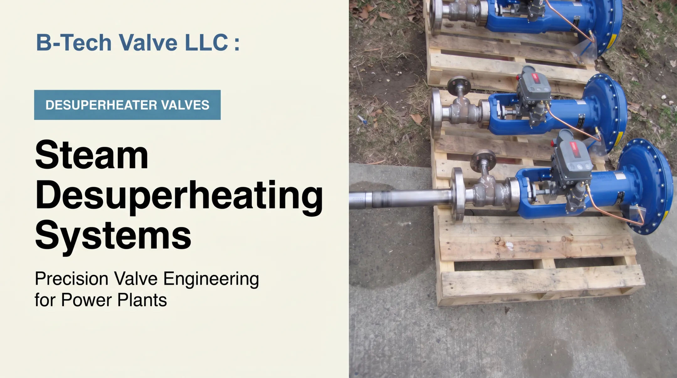
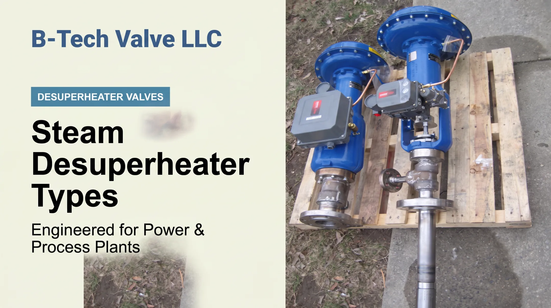
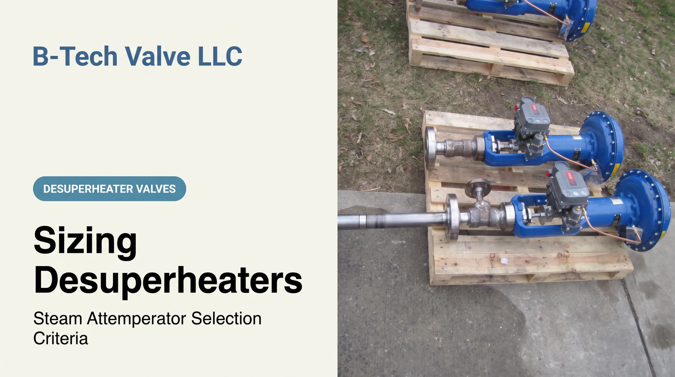
B-Tech Valve designs application-engineered desuperheater and attemperator valves for U.S. power and process plants. Final assembly and testing happen in-house, with components sourced from local U.S. machine and fabrication shops.

A calculation review with B-Tech typically looks at:
- Steam line size, pressure class, and temperature
- Flow range across minimum, normal, and maximum operating cases
- Cooling-water conditions and target outlet temperature
- Replacement timing or outage-window constraints
Two product lines cover most applications:
- LPD (6 inches and larger): Variable-nozzle actuated control valve and desuperheater in one assembly, installed through a 3-inch flanged insertion at 90 degrees
- SPAD (4 inches and smaller): Spray-ring unit that clamps between two pipe flanges and receives water from a separate temperature-control valve
Final selection still has to be confirmed against materials, pressure class, temperature rating, control range, and installation requirements for your specific application.
If you're replacing a worn-out unit during an outage or sizing a new one, reach out to B-Tech Valve at Sales@B-TechValves.com or 609-321-2205 for an application review.
Conclusion
Steam desuperheater calculations start with a steady-flow energy balance built on reliable steam and water enthalpy data, followed by careful unit conversion and a reality check against actual operating conditions.
That calculated water flow is a starting point, not a finished spec. Atomization, evaporation distance, control response, piping layout, materials, and downstream equipment protection all still need a proper engineering review before anything gets installed.
Frequently Asked Questions
How do I calculate the water flow rate?
Use the enthalpy-based energy balance: mw = ms × (hs1 − hs2) / (hs2 − hw). You'll need upstream steam flow, upstream and downstream steam enthalpies, and cooling-water enthalpy to solve it.
How do I convert steam lb/hr to condensate gpm?
Convert lb/hr using water density at the actual temperature and pressure, then divide by 60 to get gpm. Note that injected desuperheater water isn't automatically the same as plant condensate — check your actual supply source.
What information is needed to calculate desuperheater water flow?
You need steam flow, upstream pressure and temperature, the target downstream condition, cooling-water temperature and pressure, and a consistent set of units throughout the calculation.
What is the formula for calculating cooling-water flow in a steam desuperheater?
mw = ms × (hs1 − hs2) / (hs2 − hw), where hs1 is upstream steam enthalpy, hs2 is target downstream steam enthalpy, and hw is cooling-water enthalpy.
Should steam pressure be absolute or gauge pressure in the calculation?
Absolute. Steam-property tables are built on absolute pressure, so gauge readings must be converted before you look up saturation temperature or enthalpy values.
Does the calculated water flow rate fully size a desuperheater?
No. It's one sizing input. Final selection also requires flow range, pressure drop, atomization performance, line size, materials, control requirements, evaporation distance, and installation review.