Introduction
Your boiler or header runs at a pressure your process was never designed to handle. A heat exchanger rated for 150 psig sits downstream of a 600 psig main. A sterilizer needs steady, moderate pressure, not a straight shot off the plant header.
This mismatch is routine in industrial steam systems, and it's why pressure reducing stations exist.
A steam pressure reducing station is an engineered assembly that lowers and controls steam pressure while protecting the equipment downstream and keeping process conditions stable. It's more than a valve bolted into a pipe.
This article covers how these stations work, what components they need, and how to size and configure them. It also covers installation and maintenance practices, and when pressure reduction alone isn't enough: specifically when superheated steam needs a desuperheater.
Key Takeaways
- Size stations from actual operating data, not pipe diameter: flow range, pressures, steam condition, and downstream rating
- Strainers, condensate drainage, gauges, isolation, and relief protection matter as much as the valve itself
- Wide load swings or steep pressure ratios often call for staged or parallel valve arrangements
- Superheated steam may need a desuperheater after pressure reduction, not instead of it
How Does a Steam Pressure Reducing Station Work?
A reducing station sits between two pressure zones: the upstream supply (your boiler or distribution header) and the downstream process (a heat exchanger, branch line, or equipment with a lower pressure rating).
The valve holds a fixed outlet pressure, called the set point, regardless of upstream pressure swings or changes in steam flow demand.
Here's the mechanism: the reducing valve throttles flow through a restricted opening. As downstream pressure drifts from set point, the valve modulates its opening to compensate. According to TLV's steam engineering reference, the valve adjusts continuously in response to downstream pressure and demand changes.

One thing the valve cannot do: manufacture steam capacity. If your boiler or header can't supply enough flow, no reducing valve fixes that. It can only throttle what's already available.
Why Pressure Reduction Changes What Steam Can Do
Steam pressure and saturation temperature are linked. Lower the pressure, and saturated steam's temperature drops with it. That's exactly why plants reduce pressure before process heating, tracing, or sterilization applications that need cooler, gentler steam than what the main header carries.
Comparing Control Approaches
Not every station needs the same control technology. The right choice depends on load size, required precision, and whether the plant control system needs to talk to the valve.
| Control Type | Best Fit | Tradeoff |
|---|---|---|
| Direct-acting / self-acting | Smaller, steadier loads | Simple, no external power, less precise under variable demand |
| Pilot-operated | Larger or variable loads needing tighter control | Needs clean steam; small clearances are sensitive to dirt |
| Pneumatic/electric/electropneumatic | Remote adjustment, PLC/SCADA integration, fast response | Requires instrument air or power; more components to maintain |
Those control options still sit inside a full station. A reducing valve and a reducing station are not the same thing. The valve controls pressure. The station adds everything else needed to make that control safe and reliable: isolation, drainage, monitoring, and relief protection.
What Components Make Up a Steam Pressure Reducing Station?
The valve gets the attention, but a station lives or dies on its supporting components.
The Reducing or Control Valve
This is the primary control device. Its actuator, pilot, positioner, and sensing line determine how precisely and quickly it responds. A pilot-operated valve with a poorly located sensing line will hunt. A pneumatic valve without a properly specified fail-safe position creates a hazard on loss of air supply.
Isolation and Bypass Arrangements
Every station needs:
- Upstream isolation to shut off supply for maintenance
- Downstream isolation to isolate the protected process
- Bypass valves, where continuous operation is required during valve service or controlled warm-up
Condensate Management and Strainers
Wet steam entering a reducing valve causes erosion, unstable control, water hammer, and premature seat wear. The fix is upstream drainage: a drip pocket, separator, or steam trap appropriate to the system design.
A strainer belongs upstream of every reducing valve. Debris that gets past it damages pilot passages and valve seats. Screen mesh size varies by manufacturer and application. Orientation matters too: a Y-strainer in horizontal steam service needs its pocket positioned so it doesn't collect water.
Pressure Monitoring
Gauges or transmitters upstream and downstream let operators tell the difference between:
- Supply pressure variation
- Valve restriction or fouling
- Downstream demand changes
Where gauges mount in wet or hot service, siphon arrangements protect the instrument.
Downstream Overpressure Protection
If downstream piping or equipment can't handle the maximum possible upstream pressure, a relief device is required. Relief capacity assumptions matter here.
A National Board meeting attachment on pressure relief for steam reducing applications notes that sizing should consider the reducing valve failing open, plus bypass flow, not just normal operating demand.
Applicable code requirements and project specifications should guide final selection, and those requirements vary by jurisdiction and system boundary.
When a Desuperheater Belongs in the Picture
Pressure reduction alone does not guarantee a specific outlet temperature. Depending on inlet conditions, steam leaving the valve can still be superheated relative to its new, lower saturation temperature. If the process needs steam closer to saturation, or tighter temperature control, a desuperheater goes downstream of the reducing valve.

This is where B-Tech Valve's product line fits:
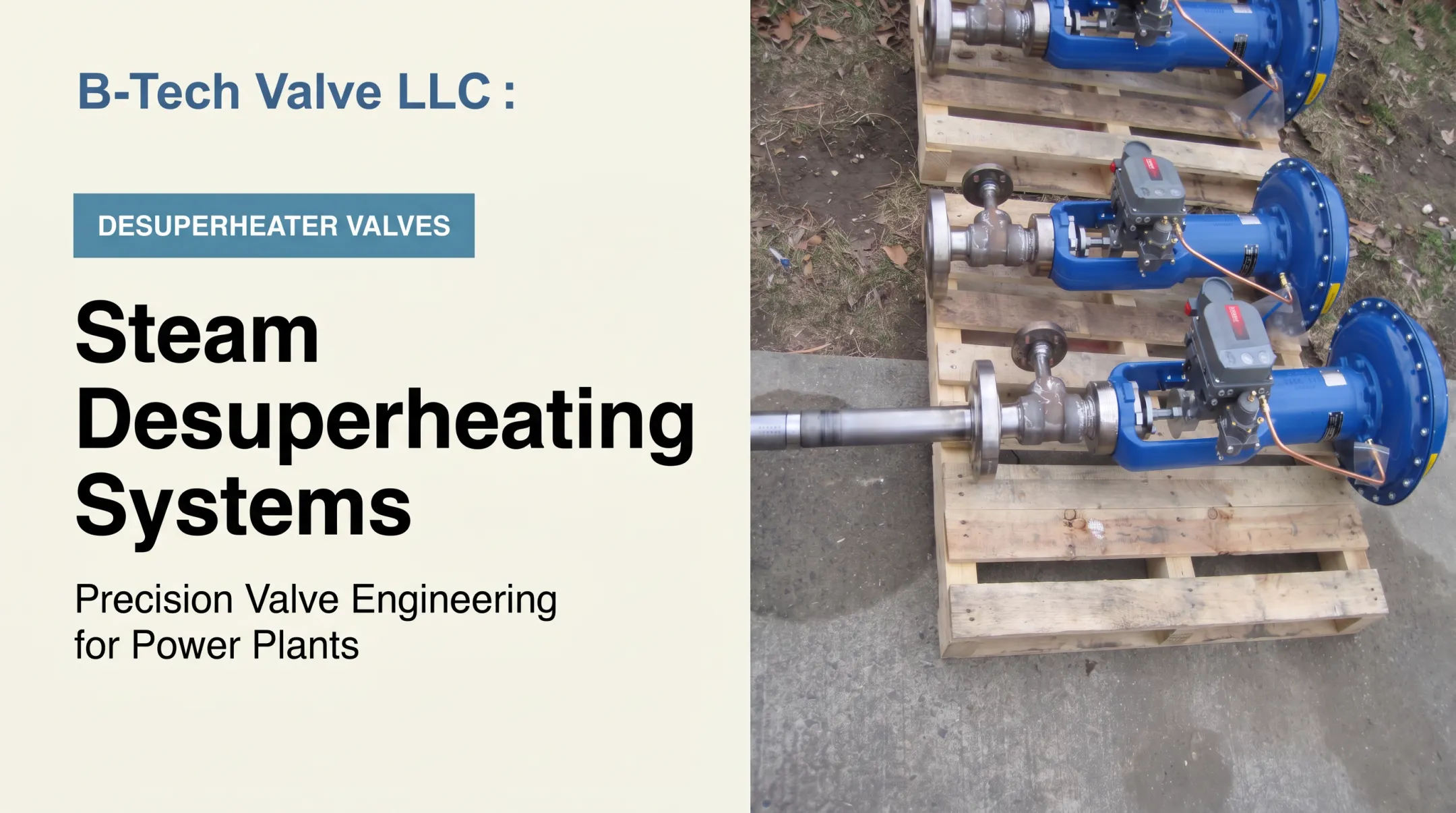
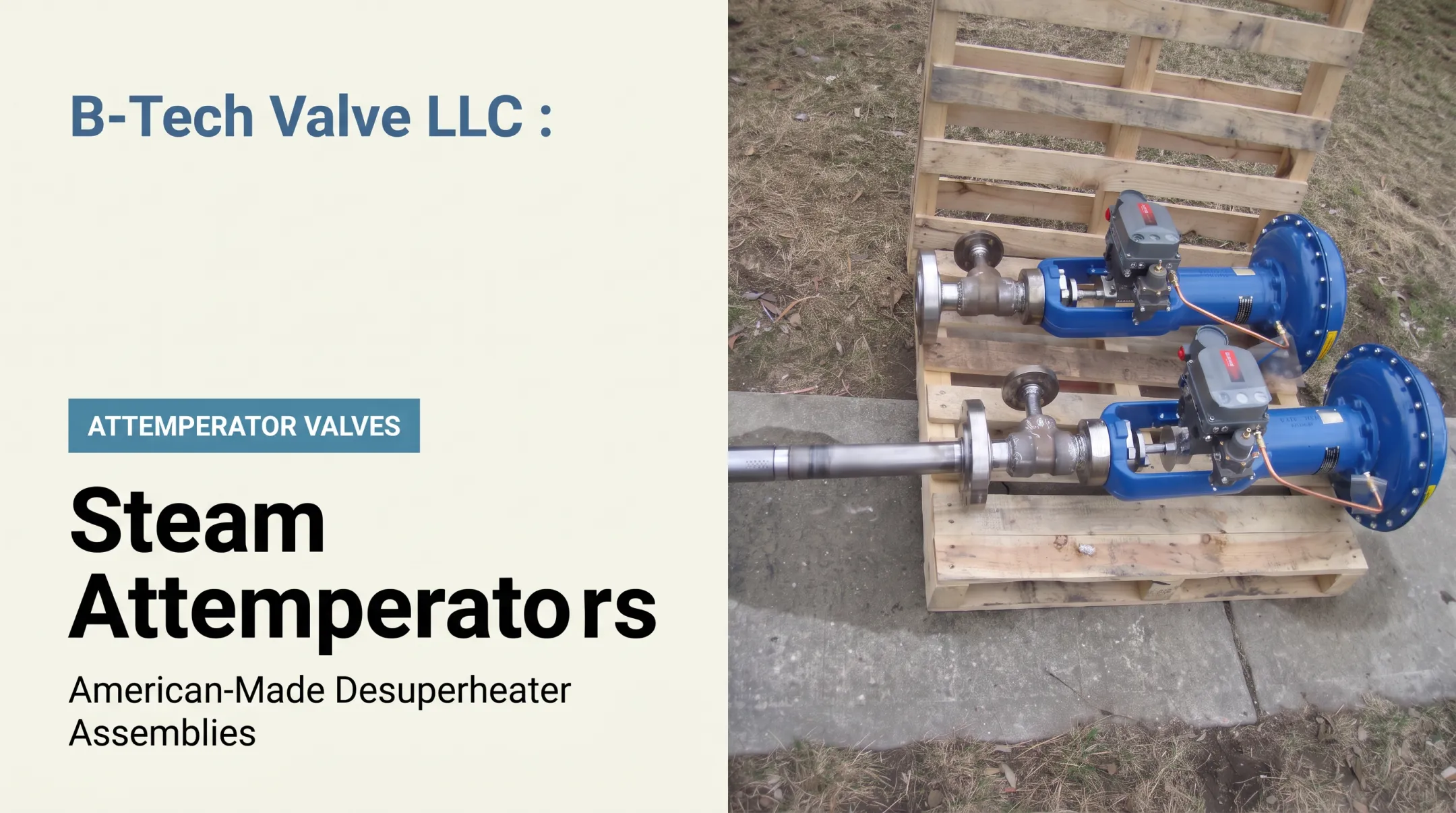
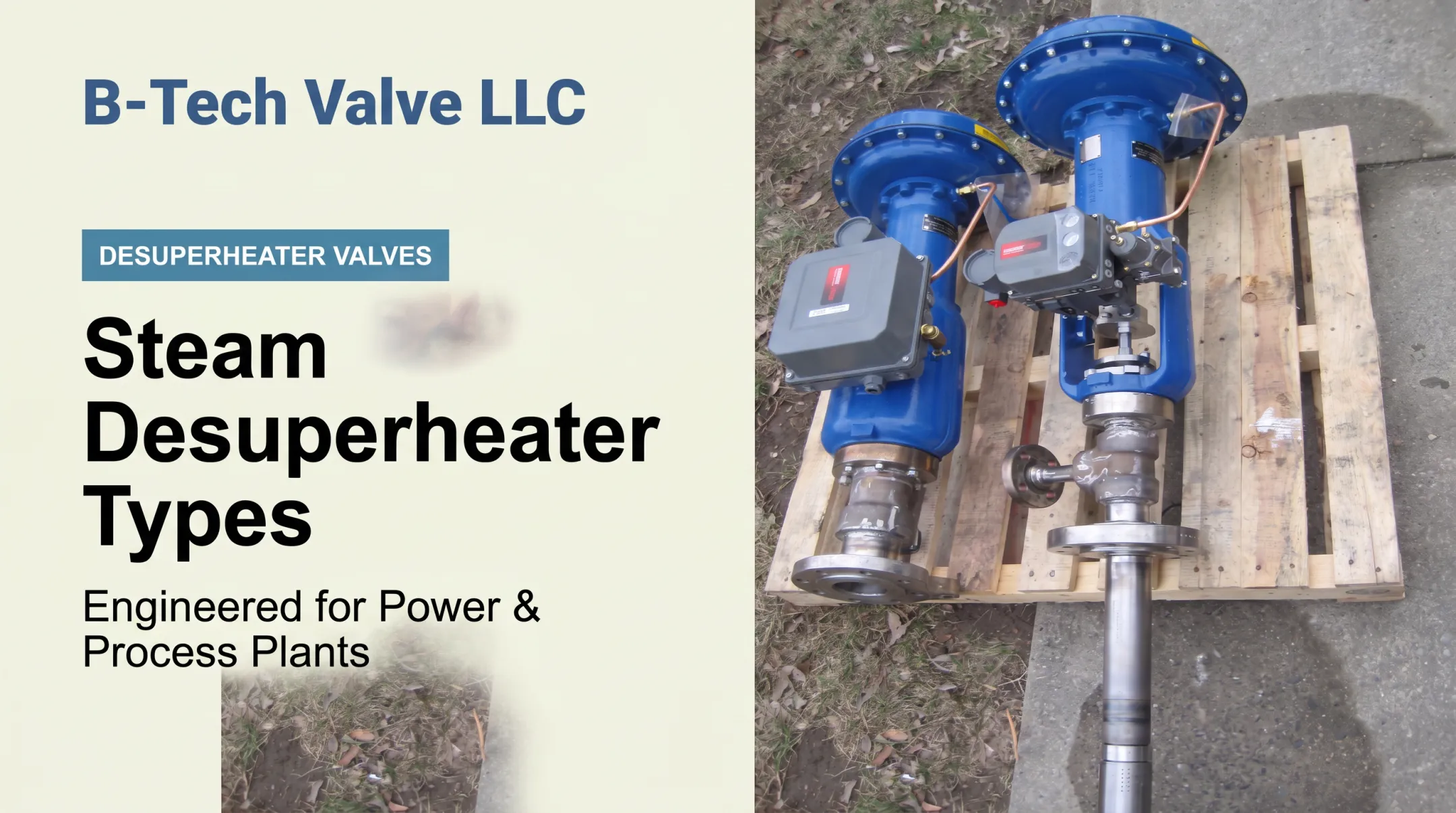
- LPD for large-pipe applications (6 inches and larger): a variable-nozzle, actuated control valve and desuperheater in one assembly, inserted through a 3-inch flanged connection
- SPAD for smaller piping (4 inches and under): a spray-ring desuperheater that clamps between two flanges and takes cooling water from a separate temperature-control valve
Confirm pressure class, temperature limits, and sizing data against B-Tech's technical documentation for your application.
How Should a Steam Pressure Reducing Station Be Sized and Configured?
Before anyone picks a valve, you need design data:
- Minimum, normal, and maximum steam flow
- Inlet pressure range
- Required outlet pressure
- Steam temperature or quality
- Allowable pressure fluctuation
- Downstream design pressure and pipe sizes
- Available utilities (instrument air, electrical power)
- Redundancy or operating requirements
Why Pipe Size Isn't a Sizing Method
Connected pipe diameter tells you nothing about a valve's actual controllable flow range. Oversizing a valve to match line size is one of the most common sizing mistakes in steam systems. It causes poor control at low load, hunting, seat leakage, and unstable outlet pressure.
Spirax Sarco's control valve sizing guidance treats minimum controllable flow and rangeability as core inputs, not pipe diameter. Get the manufacturer's actual capacity data before specifying.
Two Separate Limits to Check
- Flow range (turndown): Can one valve control both your minimum and maximum demand without hunting or losing stability?
- Pressure ratio: Is the inlet-to-outlet pressure drop appropriate for a single valve and a single stage?
When Parallel Valves Make Sense
- Wide load variation exceeds one valve's controllable range
- Critical service needs standby capacity for maintenance without shutdown
- Staged sequencing lets a smaller valve handle low demand while a larger valve covers peaks
When to Go to Series (Two-Stage) Reduction
- Very large inlet-to-outlet pressure ratios
- Excessive noise, velocity, or trim loading across one valve
- Limitations flagged in the manufacturer's own capacity data
Worked example (hypothetical, for illustration only): Say a plant needs to drop 600 psig header steam to 50 psig for process use. That's a 12:1 ratio.
Checked against a manufacturer's single-stage pressure-ratio limit of roughly 10:1 for a given valve type, this application would likely call for two stages. An intermediate reduction to about 150 psig, then a second valve down to 50 psig. Actual limits depend entirely on the selected valve and manufacturer data.

Downstream Pipe Sizing
Lower-pressure steam takes up more volume. Evaluate downstream piping for outlet velocity, noise, straight-run requirements before fittings, and sensing-line placement. Check every dimensional recommendation against the manufacturer's installation manual.
Procurement Checklist
When comparing quotes, ask every supplier to state:
- Valve type, body, and trim materials
- Pressure class and flow coefficient/capacity basis
- Minimum controllable flow and pressure-ratio capability
- Actuator and utility requirements
- Noise basis and relief assumptions
- Documentation, testing, and delivery timeline
Installation, Commissioning, and Maintenance Practices
Good piping practice starts before the valve ever sees steam:
- Appropriate horizontal run
- Upstream condensate drainage
- Correctly oriented strainer
- Accessible isolation valves and gauges
- Safe relief discharge routing
Startup and Warm-Up
- Warm downstream piping gradually and under control
- Do not use the main reducing valve as an uncontrolled warm-up device unless the manufacturer explicitly allows it
- Open isolation valves and bring the station to set point following the approved operating procedure
Commissioning Checks
Before calling a station ready for service, verify:
- Inlet and outlet pressure under actual load
- Set point accuracy
- No hunting or excessive noise
- Strainer condition
- Trap operation
- Alarm and transmitter function
- Documented baseline readings for future reference
Troubleshooting Quick Reference
| Symptom | Common Causes |
|---|---|
| Low outlet pressure | Undersized valve, insufficient inlet pressure, worn trim |
| High outlet pressure | Valve stuck open, failed pilot, debris holding seat open |
| Unstable control | Operating below minimum controllable flow, poor sensing-line placement |
| Excessive noise | Oversized valve, high pressure ratio, inadequate downstream piping |
| Recurring condensate/debris | Failed trap, missing separator, strainer not maintained |
Always isolate and follow site safety procedures before inspecting any component.
Maintenance
Base inspection intervals on service severity and manufacturer guidance rather than a fixed calendar schedule. Regularly inspect:
- Trim, seats, and pilots
- Sensing lines and instrumentation
- Strainers and traps
- Relief devices and bypass valves
New lines and units coming off extended outages deserve extra attention on the first run.
Choosing Pressure Reduction and Desuperheating Equipment for US Plants
Before specifying equipment, work through a short comparison:
- What outlet pressure does the process actually need?
- What's the saturation temperature at that pressure, versus the actual steam temperature?
- What's the process temperature limit?
- How much does load vary, and how fast must the system respond?
These answers tell you whether the project needs pressure reduction alone, pressure reduction plus desuperheating, or a separate temperature-control loop entirely.
A pressure reducing valve throttles flow to lower pressure. A desuperheater injects controlled water to remove superheat. Neither substitutes for the other. A plant that specifies only a PRV when the process also needs tighter temperature control will end up with steam that's technically at the right pressure but still too hot to use.

B-Tech Valve LLC, based in Palmyra, New Jersey, designs application-engineered steam and gas desuperheater and attemperator valves for power and process plants across the country. The company's two core product lines cover most line sizes plants encounter:
- LPD: a probe-type, variable-nozzle, fully actuated control valve and desuperheater combined in one assembly, built for steam pipes 6 inches and larger
- SPAD: a spray-ring, fixed-nozzle desuperheater for pipes 4 inches and smaller, paired with a separate temperature-control valve
Both are offered in ASME B16.34 pressure classes 150 through 2700, with temperature ratings to 1,200°F. Confirm current materials, water-quality requirements, and sizing specifics against B-Tech's technical documentation for your project before finalizing a specification.
If you're a plant engineer, EPC team member, valve distributor, or outage contractor working through a steam conditioning problem, B-Tech's application engineering team reviews steam flow, pressure, temperature, pipe size, and process requirements directly. Reach out through B-Tech Valve's contact page or email Sales@B-TechValves.com with your application details.
Frequently Asked Questions
How to reduce steam pressure?
Industrial steam pressure is reduced with a correctly sized pressure reducing valve or control valve installed within a complete station. Selection depends on inlet pressure, target outlet pressure, steam flow, downstream equipment rating, and required control performance.
What is included in a steam pressure reducing station?
A complete station includes the reducing valve, upstream and downstream isolation valves, pressure gauges or transmitters, a strainer, condensate drainage, bypass or warm-up provisions where needed, and downstream overpressure protection.
How do you size a steam pressure reducing station?
Sizing requires minimum and maximum flow, inlet and outlet pressures, steam condition, pressure ratio, downstream pressure rating, and allowable noise or velocity limits, checked against the selected manufacturer's actual capacity data rather than pipe size.
When is two-stage steam pressure reduction required?
Two stages are typically needed for high pressure ratios, excessive noise or velocity across one valve, or turndown limits identified in manufacturer data. This differs from parallel valves, which address flow range or redundancy, not pressure ratio.
Does a pressure reducing valve also reduce steam temperature?
Lowering pressure lowers saturation temperature, but superheated steam can remain hotter than the new saturation point after reduction. If the process needs steam closer to saturation, a properly sized desuperheater is required downstream.
What causes unstable pressure downstream of a reducing station?
Common causes include incorrect valve sizing, operation below the valve's minimum controllable flow, wet steam, clogged strainers or pilots, poor sensing-line placement, fluctuating supply pressure, or inadequate downstream piping.