That dual role creates a real engineering puzzle. A plant has to balance electrical output against steam pressure, temperature, and flow, often while downstream equipment can't tolerate steam that's too hot or too dry. Get it wrong, and you risk thermal shock, damaged piping, or an unreliable process.
This article walks through what a CHP plant is, how fuel becomes electricity and usable steam, how that steam gets conditioned for the process floor, and what engineers and plant owners should weigh before specifying equipment.
Key Takeaways
- Cogeneration, CHP, and combined heat and power all describe producing electricity and useful heat from one fuel source
- Process steam can come from an HRSG, a boiler, turbine extraction, backpressure operation, or a mix of these
- Steam conditioning equipment keeps delivered steam within the pressure and temperature range downstream equipment needs
- CHP delivers the most value when a facility has steady, economically useful demand for both power and heat
What Is a Cogeneration (CHP) Plant?
Cogeneration and combined heat and power (CHP) describe the same thing: a system that uses one fuel source to produce electricity and usable heat, rather than rejecting that heat to the atmosphere. This is the core distinction from a conventional setup, where a facility buys or generates its electricity separately and runs an independent boiler just for process heat. CHP links those two needs together in a single energy flow.
Prime Movers and Heat Recovery
Every CHP plant needs a prime mover to convert fuel or steam energy into mechanical power, a generator to turn that power into electricity, and heat-recovery equipment to capture what's left.
| Prime mover | Role |
|---|---|
| Reciprocating engine | Converts fuel combustion into shaft power; exhaust and jacket-water heat are recovered separately |
| Gas turbine | Converts fuel combustion into shaft power; hot exhaust is routed to a heat-recovery steam generator (HRSG) |
| Steam turbine | Converts boiler steam energy into shaft power; extraction or backpressure steam serves process loads |
Heat-recovery equipment varies by system, and typically includes exhaust heat exchangers, HRSGs, boilers, or process heat exchangers that transfer thermal energy to the steam or hot-water loop a facility actually uses.
Topping Cycles vs. Bottoming Cycles
Most industrial CHP installations are topping cycles: the prime mover generates power first, and the leftover exhaust or cooling heat is recovered afterward for process use. A bottoming cycle runs the opposite direction. High-temperature process waste heat, say, from a kiln or furnace, drives a generator (often a steam turbine) after the industrial process has already used that heat for its primary purpose.
CHP can achieve overall efficiencies above 80%, compared with roughly 50% for electricity purchased from the grid paired with a separate on-site boiler, according to EPA's CHP program. That efficiency gain is the whole point of pairing power generation with heat recovery instead of treating them as separate problems.

How CHP Plants Produce Process Steam
The basic path runs from fuel input to useful output: combustion or steam expansion generates mechanical power, the generator converts that to electricity, and recovered heat becomes steam delivered to process users. How that happens depends heavily on which prime mover sits at the center of the plant.
Gas-Turbine Systems
In a gas-turbine CHP plant, hot exhaust gas routes through an HRSG, which generates high-pressure or lower-pressure steam for process use, additional power generation, or both.
A 25 MW gas turbine paired with an unfired HRSG can produce roughly 29 MWth of process steam. That figure assumes dry, saturated steam at 150 psig, according to EPA's turbine catalog. Higher steam pressures are achievable, though they typically come with a slight efficiency trade-off.
Reciprocating-Engine Systems
Reciprocating engines recover heat from several circuits:
- Exhaust gas
- Jacket water
- Lubrication systems
- Turbocharger cooling (in some setups)
Exhaust is the hottest stream and the most practical source for steam generation. Jacket water and lube-oil heat often run too cool for steam and instead support hot water or thermal-oil loops. Usable output depends entirely on which circuit you pull from.
Steam-Turbine Systems
Steam-turbine CHP arrangements fall into two broad categories:
- Backpressure turbines exhaust steam directly to a process main at the pressure the downstream load requires
- Extraction-condensing turbines pull steam from an intermediate stage, sending the rest onward through the turbine for additional power generation
Typical steam distribution pressures land around 50, 150, and 250 psig, though actual discharge pressure is set by the specific application, not a fixed industry number. From there, steam typically moves through pressure-reducing stations and temperature control before reaching headers, heat exchangers, dryers, reactors, or sterilization equipment.
Matching Output to Thermal Load
Electrical demand and steam demand rarely rise and fall together. A facility might need steady steam for a continuous process while electrical load swings with shift changes or weather.
Startup, shutdown, and seasonal shifts complicate the picture further. Plants that don't account for this mismatch end up venting excess steam, running supplemental boilers more than planned, or throttling output in ways that hurt overall economics.
Process Steam Conditioning and Desuperheater Selection
Steam coming out of an HRSG or boiler often runs hotter or drier than a downstream process can tolerate. Sending it straight to a heat exchanger or reactor risks poor heat transfer, thermal shock, or outright damage to piping and seals.
That's where desuperheating, also called attemperation, comes in: controlled injection of treated water that pulls steam temperature down to the operating condition the process actually needs.
It sounds simple. It isn't. Pressure, water quality, mixing distance, and evaporation all have to be engineered together, or the result is water carryover instead of properly conditioned steam.

Information to Gather Before Selecting a Unit
Before specifying or replacing a desuperheater, engineers should document:
- Upstream and downstream steam pressure and temperature
- Minimum, normal, and maximum steam flow, plus line size and steam quality
- Available spray-water pressure and temperature
- Turndown requirements
- Material requirements and control-valve or actuator details
Turndown matters more than it might seem. A unit has to perform reliably at startup and low load, not just at the full-flow condition used for the original sizing calculation. A desuperheater sized only for peak flow can struggle, or fail outright, during the exact conditions where process reliability matters most.
Installation and Control Considerations
Getting the hardware right isn't enough on its own. Installation and control details that affect real-world performance include:
- Adequate straight-run or mixing distance downstream of the injection point
- Spray-water atomization quality
- Temperature-sensor placement and control-loop response time
- Drainage and insulation
- Protection against water carryover into downstream piping or equipment
Where B-Tech Valve Fits
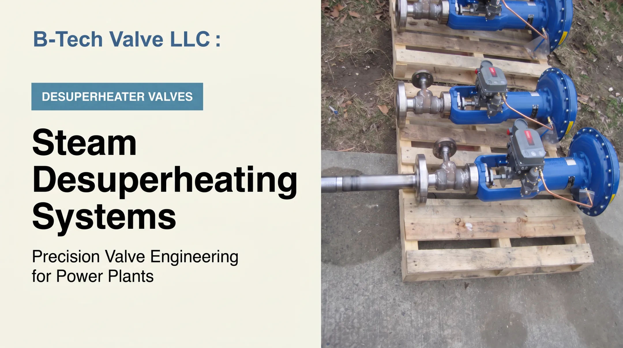
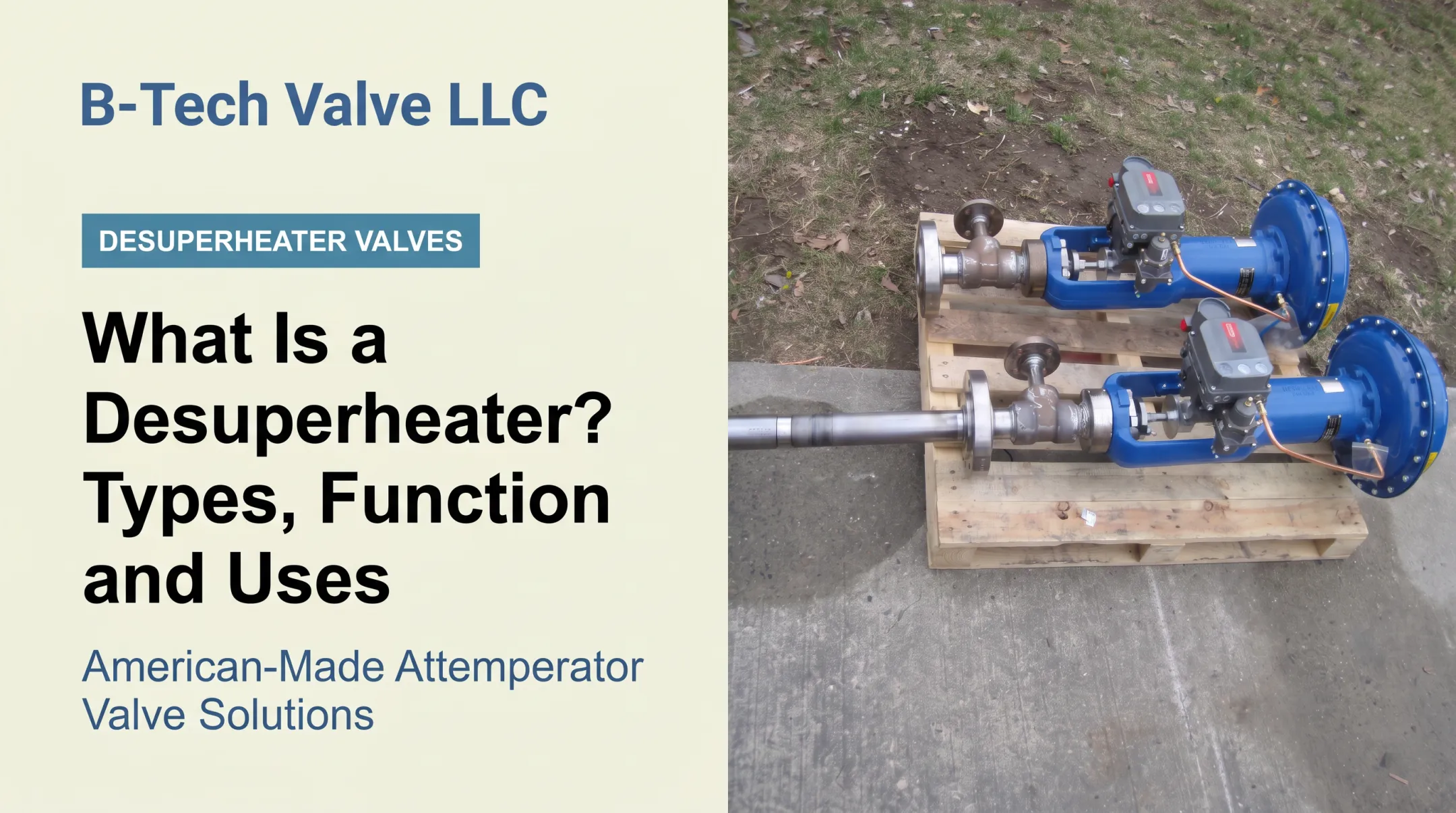
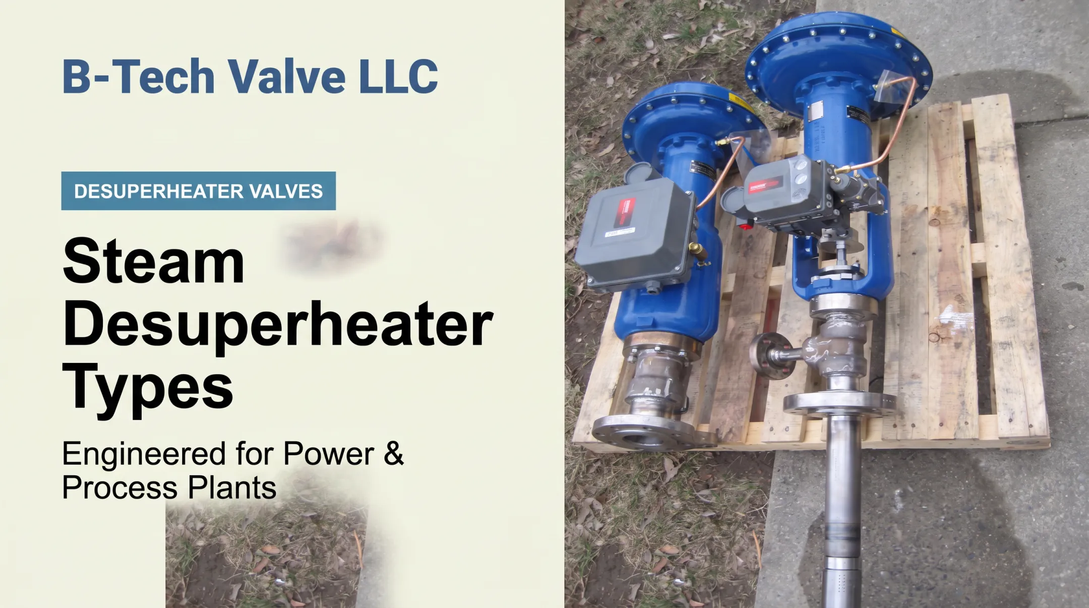
B-Tech Valve designs and builds American-made, application-sized desuperheater and attemperator assemblies for power and process plants, including CHP installations. Two product lines cover most steam-line sizes:
- The LPD Large Pipe Desuperheater is a probe-type, variable-nozzle, fully actuated control-valve and desuperheater assembly built for steam pipes 6 inches and larger
- The SPAD Small Pipe Attemperator Desuperheater is a spray-ring unit for steam pipes 4 inches and smaller, paired with a separate temperature-control valve
Neither is a one-size-fits-all product; each installation gets reviewed against its actual operating conditions. B-Tech Valve's components are sourced from U.S. machine and fabrication shops, with final assembly and testing done in-house, and products are stocked to shorten turnaround when a plant needs a replacement fast.
A Practical Selection Sequence
- Establish the process steam requirement (pressure, temperature, flow range)
- Confirm the full operating envelope, including startup and turndown conditions
- Evaluate water injection and mixing requirements
- Verify materials and pressure class against ASME B16.34 ratings
- Review controls, instrumentation, and maintenance access
- Obtain a manufacturer's sizing recommendation before finalizing specifications
CHP Applications, Benefits, and Project Considerations
Process-steam CHP shows up across a wide range of facilities: refineries, chemical plants, pulp and paper mills, food and beverage plants, hospitals, universities, district-energy systems, waste-to-energy facilities, and large industrial campuses. What ties them together is a steady, year-round need for both power and thermal energy.
Benefits Worth Weighing
- Reduces fuel waste by capturing heat that would otherwise be rejected
- Supplies on-site power and cuts reliance on purchased electricity
- Lowers boiler fuel use by delivering steam without a separate combustion source
- Puts existing thermal loads to work instead of rejecting usable heat
Limitations and Risks
CHP isn't automatically a good fit everywhere. Common risks include:
- An uneven heat-to-power ratio relative to the facility's actual needs
- Insufficient or intermittent process-steam demand
- Fuel-price exposure and emissions permitting requirements
- Water treatment, controls integration, and ongoing maintenance demands
- Grid interconnection requirements and the need for backup or supplemental boilers
An Evaluation Framework
Before specifying equipment, facility owners and designers should:
- Compare hourly electricity and steam demand profiles against the proposed system's output
- Evaluate steam pressure levels, process criticality, redundancy, and bypass arrangements
- Account for condensate recovery, startup conditions, and anticipated production changes
- Consider lifecycle factors: replacement-part availability, outage scheduling, domestic sourcing, and inspection access for steam-conditioning equipment
Thermal and electrical load profiles determine system sizing and operating strategy. Power-to-heat ratio is a key metric for judging prime-mover suitability, according to DOE's CHP handbook.
Start with measured load data, not assumptions. Bring in qualified CHP, boiler, turbine, controls, and steam-conditioning professionals before making payback claims.
Frequently Asked Questions
How does cogeneration work?
One fuel source generates electricity through a prime mover, and the heat that would otherwise be wasted gets recovered and used as process steam, hot water, or another thermal load. Both outputs come from the same combustion or steam-expansion event.
What is a cogeneration plant?
A cogeneration plant generates electrical power and usable heat at the same time. It typically pairs a reciprocating engine, gas turbine, or steam turbine with heat-recovery equipment such as an HRSG or heat exchanger.
Is cogeneration the same as combined heat and power (CHP)?
Yes, the terms are generally interchangeable. Specific system configurations, prime movers, and applications can still vary quite a bit from one CHP plant to another.
What is the difference between a cogeneration plant and a combined-cycle power plant?
CHP's defining feature is delivering useful thermal energy to a process or customer. A combined-cycle plant uses gas-turbine exhaust to generate additional electricity through a steam cycle, with no requirement to supply usable heat elsewhere.
What is natural gas cogeneration?
Natural gas cogeneration is a CHP system fueled by natural gas. A gas turbine or reciprocating engine drives power generation, and recovered exhaust or cooling heat becomes steam or hot water for process use.
What is a gas turbine cogeneration system?
A gas turbine generates electricity while its hot exhaust routes through an HRSG, producing process steam or other usable thermal energy instead of venting that heat to the atmosphere.