Introduction
A steam header looks like a big pipe. It's actually one of the most consequential components in a power or process plant's steam system.
Its layout affects steam quality, how boilers share load, pressure stability, condensate removal, and whether downstream equipment survives the next decade or fails early. Get the header wrong, and every piece of equipment downstream pays for it.
The desuperheater raises a related design question: where does spray water get a fair chance to fully evaporate and mix with steam before that conditioned steam reaches a turbine, process heat exchanger, or pressure-reducing station? Placement mistakes here show up as wet steam, erosion, or unreliable temperature control.
This guide covers header flow direction, off-take and drain arrangement, desuperheater placement, control instrumentation, and the application-specific decisions that matter for US power and process plants.
Key Takeaways
- A steam header should promote balanced flow, dry-steam delivery, controlled warm-up, and reliable condensate removal.
- Desuperheaters need a well-mixed pipe section upstream of the user, plus enough downstream run for evaporation and accurate sensing.
- Drain pots, separators, traps, isolation valves, and temperature instruments form one complete steam-conditioning station.
- Final dimensions depend on pressure, temperature, flow, steam quality, spray-water conditions, and applicable engineering standards.
Steam Header Design Fundamentals
A steam header's job depends on where it sits. A boiler header collects steam directly from one or more boiler risers and feeds it toward the plant distribution system. A main distribution header takes that steam and routes it to multiple off-takes serving turbines, process units, and heating loads.
Both manage the same core functions:
- Collecting steam and supporting load sharing between boilers
- Supplying off-takes without starving any one branch
- Giving moisture somewhere to go
Sizing, Velocity, and Multi-Boiler Balance
Header diameter, velocity, and pressure drop aren't independent decisions. They have to be evaluated together, against the governing piping code for the installation.
- ASME B31.1 covers power and industrial piping, including defined boiler-external piping.
- ASME B31.3 explicitly covers steam piping in process plants.
- Confirm which code (and which boiler/piping boundary) applies before sizing anything.
For multi-boiler arrangements, pressure-drop balance between each boiler outlet and the plant take-off matters more than matching nominal branch sizes. Spirax Sarco's steam guide notes that a centered-discharge layout, properly sized, limits boiler overload risk significantly compared to an unbalanced header arrangement.
Off-Takes, Drains, and Flow Direction
Dry-steam off-takes should come from the top of the header. Side and bottom branches pull in condensate and debris sitting in the pipe. Low points need deliberate drain pockets and traps, not incidental sag in the pipe run.
Multi-boiler geometry introduces its own risks:
- System take-offs placed between boiler risers can starve one boiler while overloading another
- Opposing boiler flows directed toward each other create turbulence and uneven pressure
- Header terminations that let steam double back can re-entrain moisture just collected
A practical multi-boiler layout includes:
- Boiler inlets on each end with flow meeting at a centered off-take
- Top-mounted steam branches and bottom drain pockets at low points
- Isolation and check valves on each boiler riser
- An equalizing path sized for the plant's actual load swing
The final arrangement also has to account for:
- Boiler sequencing and isolating an offline boiler
- Thermal expansion, pipe supports, and maintenance access
- Warm-up sequencing and failure modes if a valve or control fails
Skipping any of these during design tends to surface as an operational headache later.

Where to Place a Desuperheater in a Steam System
A desuperheater injects controlled spray water into superheated steam to pull the temperature down toward whatever the downstream equipment requires, without sacrificing usable pressure or steam quality. That's the easy part to describe. Placement is where projects go wrong.
Mapping the Installation Sequence
A typical steam-conditioning station runs in this order:
- Steam source (boiler or header branch)
- Pressure-reducing or isolation equipment, if present
- Desuperheater injection point
- Downstream mixing and evaporation length
- Temperature sensor
- Drain provisions
- Final process or power-plant user
Every link in that chain affects the one after it. A pressure-reducing station upstream of the desuperheater changes steam velocity and saturation temperature at the injection point, which changes how much spray water is needed.
Why Location Beats Convenience
The desuperheater has to go where temperature actually needs controlling, not at whichever header nozzle happens to be easiest to tap into. Load swings, spray-water pressure, steam velocity, and required turndown all shift the ideal location.
Downstream mixing distance is manufacturer-specific. There's no single generic number that works across designs. Spirax Sarco's steam guide notes that required sensor distance depends on the desuperheater type and the size of the temperature change requested. A sensor placed too close reads before mixing finishes.
In a sound layout, steam enters from upstream, passes the desuperheater injection point, travels through a mixing and evaporation zone, then reaches a temperature sensor and drain pot before the protected equipment (turbine, heat exchanger, or process header).
Installing the unit too close to an elbow, tee, valve, reducer, or header outlet creates real problems:
- Uneven water distribution
- Direct impingement on the pipe wall
- Unreliable temperature readings
- Localized erosion
- Spray water that never fully vaporizes before reaching the user
Placement also differs by application. Process steam users typically tolerate more mixing length than turbine protection schemes, where rotating-equipment damage from wet steam is far more costly. Downstream of pressure-reducing stations, the desuperheater may be integrated directly with the control valve, or installed as a separate spray device. That choice depends on line size, pressure drop, and turndown needs.

Integrating Header, Desuperheater, Controls, and Drains
Header pressure and flow disturbances don't stay contained to the header. They ripple into spray-water atomization, steam mixing quality, control-valve response time, and the accuracy of temperature measurement right at the desuperheater.
Instrumentation and Control Functions
A complete steam-conditioning station needs several things evaluated together, not in isolation:
- Upstream and downstream pressure and temperature sensing
- Steam-flow measurement where turndown or load swings are significant
- Spray-water flow control and isolation valves
- Defined fail-safe positions for every control element
- High-temperature alarms and low-temperature or wet-steam protection
Point-of-use pressure sensing matters when the control scheme needs to compensate for line losses between the desuperheater and the actual user.
Drainage and Transient Operation
Drainage downstream of a desuperheater carries its own urgency. Spray-water leakage, startup condensate, and low-load condensation all have to go somewhere: usually a properly sized drain pot, not an afterthought fitting.
Transients are where most problems actually occur. EPRI's water-induction report found that roughly three-quarters of water-induction incidents in steam turbines happen during startup, shutdown, trips, load reduction, or turning-gear operation — not steady-state running.
That means drain valves and temperature controls need defined responses for each operating mode:
- Startup: drains open, temperature detection active before load increases
- Shutdown: block valves confirmed closed, condensate paths verified clear
- Trip: automatic isolation of spray water, independent of the main control loop
- Low load: monitoring for condensation that steady-state logic might miss
Worst-case reviews should also cover:
- Maximum spray-water flow
- A stuck-open control valve
- Loss of instrument air or power
- Rapid load changes
- A blocked or undersized drain path
A qualified engineer needs to verify thermal mixing, pressure drop, two-phase flow behavior, material compatibility, and relief or venting needs against the station's actual pressure and temperature class, not a simplified steady-state case.
Choosing a Desuperheater for Header and Process Conditions
Selecting between a probe-type unit, a spray-ring design, or an integrated control-valve/desuperheater assembly comes down to a handful of application factors:
- Pipe size and available insertion length
- Steam pressure, temperature, and flow range
- Required outlet temperature and allowable tolerance
- Available spray-water pressure (it must exceed steam pressure at the injection point)
- Turndown needed across the operating range
Line Size Drives the Configuration
Line size alone tends to point toward one design family or another.
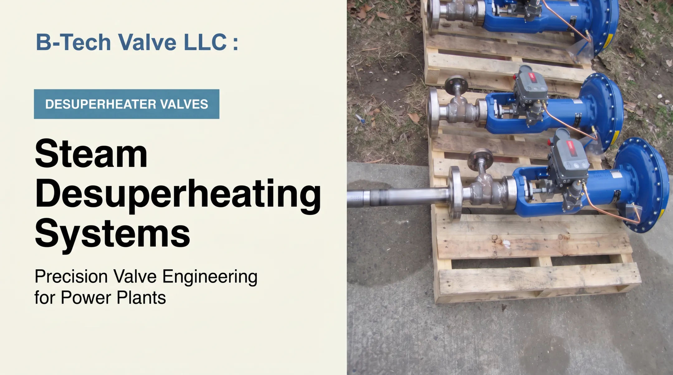
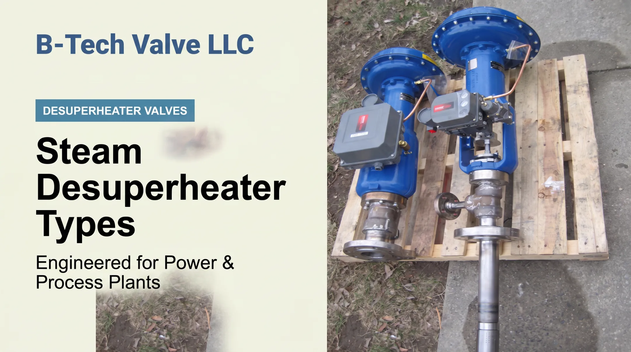
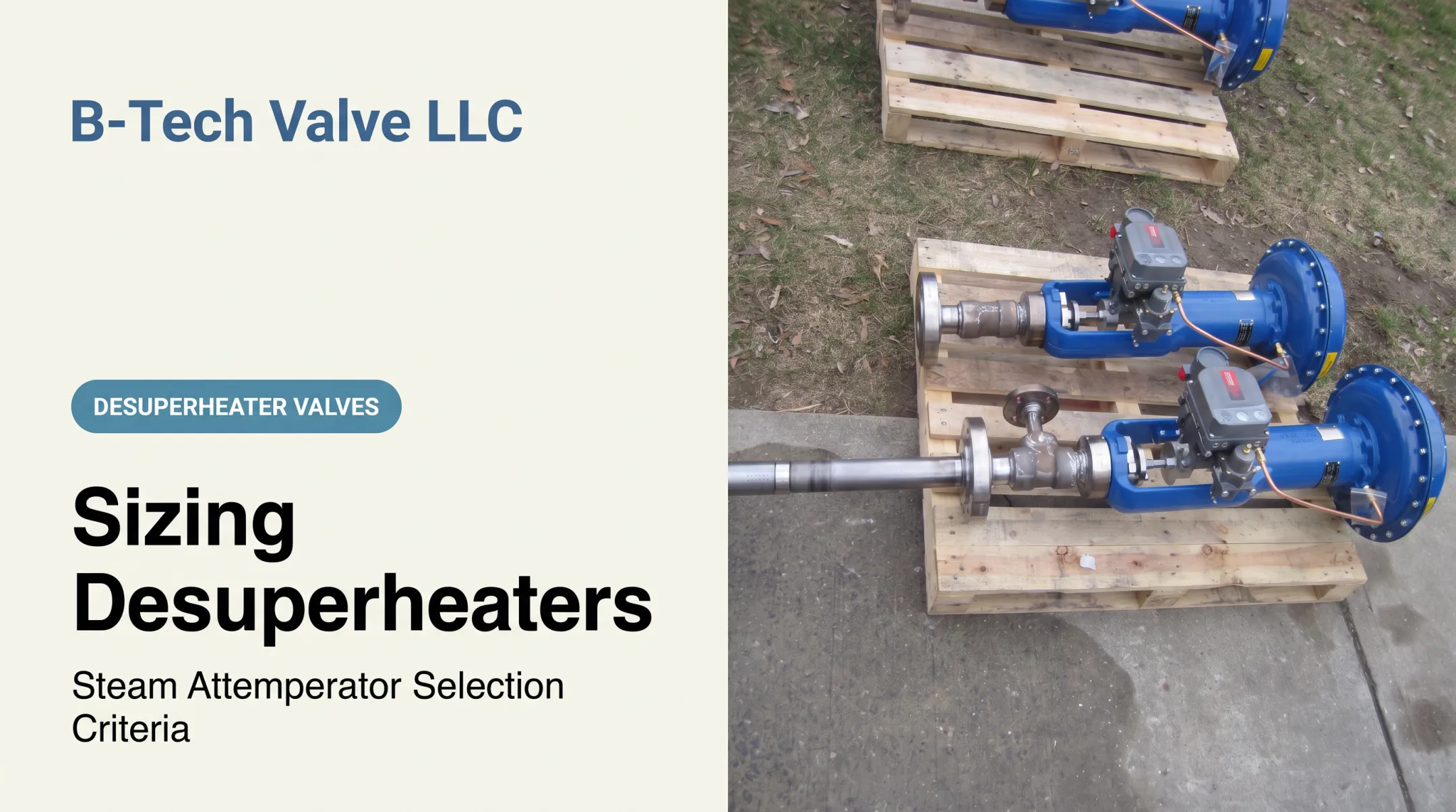
B-Tech Valve's LPD is a probe-type, variable-nozzle unit built for steam pipes 6 inches and larger. It combines a fully actuated control valve and desuperheater in one assembly that inserts through a 3-inch flanged connection at 90 degrees on the pipe side.
For smaller lines, the SPAD spray-ring design, built for steam pipes 4 inches and smaller, clamps between two steam-pipe flanges and takes its feed water from a separate temperature-control valve.
Both are American-made and sized to the customer's actual operating conditions rather than pulled from a generic catalog. B-Tech Valve offers them in ASME B16.34 pressure classes 150 through 2700, for temperatures up to 1,200°F. Confirm current documentation against your project's design conditions before specifying anything.

If you're a power plant, process facility, EPC engineer, distributor, or outage contractor evaluating a replacement or new installation, send B-Tech Valve your steam pressure, temperature, flow, pipe size, spray-water conditions, and required outlet temperature.
Their application engineering team can review sizing against your actual conditions rather than a generic data sheet.
Common Steam Header and Desuperheater Placement Mistakes
Most header and desuperheater problems trace back to a short list of repeat offenders.
Header-level mistakes:
- Undersized headers that force high velocity across the whole load range
- Poorly positioned tees that create uneven flow splits
- Opposing boiler flows directed into one another
- Side or bottom off-takes that entrain condensate
- Missing low-point drains
- Inadequate warm-up provisions for cold starts
Desuperheater-specific mistakes:
- Installing immediately downstream of an elbow, tee, or valve
- Insufficient mixing length before the temperature sensor
- Poor sensor placement that reads wetted or disturbed flow
- Inadequate spray-water quality or pressure
- No provision for draining downstream leakage
Field-Review Checklist
Before finalizing a design, walk through:
- Flow direction at every branch and off-take
- Pipe supports and thermal expansion allowance
- Valve and instrument access for maintenance
- Insulation coverage, including around sensors
- Drain-pot capacity versus expected condensate load
- Isolation provisions for each boiler and user
- Startup logic and documentation of the final design
Safety note: Header and desuperheater work involves high-pressure, high-temperature steam. All design, installation, testing, and commissioning must be handled by qualified personnel following applicable US codes, plant procedures, and manufacturer instructions.
Frequently Asked Questions
What is a steam header?
A steam header is a piping assembly or vessel that collects steam from one or more boilers and distributes it to downstream uses. It supports pressure management, steam quality, boiler load sharing, and condensate control.
What is the difference between steam and condensate?
Steam is the vapor phase used to transport heat; condensate is the liquid water that forms once steam loses heat. The distinction drives drainage design, water-hammer prevention, and how a desuperheater's downstream drains are sized.
What is the correct arrangement for steam and condensate pipework?
Steam should flow in a defined direction, with top-mounted off-takes for dry steam and piping sloped toward low-point drain pots or traps. Include isolation valves at takeoffs and confirm the layout with application-specific engineering review.
Can you use schedule 40 pipe for steam?
Schedule selection depends on pressure, temperature, material, corrosion allowance, code requirements, and joining method. Don't select pipe schedule from nominal size alone; run the design calculation for your actual conditions.
What is the main purpose of a steam boiler?
A steam boiler transfers heat into water to produce steam for power generation, process heating, or facility services. Headers and desuperheaters then condition and distribute that steam for safe, usable downstream delivery.