Natural gas combined-cycle plants account for roughly 291,808 MW of the United States' 1,230,414 MW of total utility-scale net summer capacity, based on 2024 data from the EIA's Electric Power Annual. That's close to a quarter of the entire US generating fleet running on this technology.
Despite how common these plants are, their diagrams confuse plenty of engineers and technicians on first read. Multiple loops, turbines, generators, heat exchangers, pumps, and control points overlap on a single page. This guide walks through each flow path, starting with fuel and air and ending with electricity hitting the grid.
Key Takeaways
- A combined cycle plant pairs a gas-turbine topping cycle with a steam-turbine bottoming cycle
- The Heat Recovery Steam Generator (HRSG) captures gas-turbine exhaust heat to produce additional steam power
- Read diagrams through four separate paths: gas, water-and-steam, electrical, and exhaust
- Configuration, ambient conditions, condenser performance, and steam control all shape output and efficiency
What Is a Combined Cycle Power Plant?
A combined cycle power plant converts fuel energy into electricity using two connected thermodynamic cycles rather than one. The gas turbine runs first; its leftover exhaust heat then powers a second generation stage instead of going to waste.
The first cycle (gas turbine, or Brayton cycle):
- Compresses incoming ambient air
- Burns fuel in a combustion chamber
- Expands the hot combustion gases through turbine stages
- Drives a generator directly connected to the turbine shaft
The second cycle (steam, or Rankine cycle):
- Captures gas-turbine exhaust heat in the HRSG
- Converts feedwater into steam using that recovered heat
- Expands the steam through a separate steam turbine
- Drives a second generator for additional electrical output
How the Cycles Connect
The gas and steam cycles share a direct energy connection through the HRSG. An HRSG also differs from a conventional fired boiler: it primarily recovers heat already present in turbine exhaust rather than burning fuel independently (though supplementary firing is sometimes added, more on that below).
Common Plant Configurations
Diagrams vary depending on how many gas turbines, HRSGs, steam turbines, and generators the plant uses. The EIA notes that the most common arrangement, labeled 2x1, pairs two combustion turbines with a single steam turbine. Other configurations exist too, including single gas-turbine setups paired one-to-one with a steam turbine. Always check the specific plant's legend before assuming component counts. Manufacturer drawings differ.

How Does a Combined Cycle Power Plant Work?
Think of the diagram as a sequence, not a static picture. Air and fuel enter on one side. Gas-turbine exhaust transfers heat in the HRSG. Steam drives a second turbine. Condensed water loops back to start the steam cycle again.
Diagram Reading Guide
Before tracing any flow lines, locate these components first:
- Gas turbine and its generator
- HRSG (often drawn as a long, segmented box)
- Steam turbine and its generator
- Condenser and feedwater pumps
- Cooling system (tower, once-through, or air-cooled)
- Fuel and air inlets, exhaust stack
- Steam lines and electrical output points
Once you've spotted these, follow four distinct paths through the drawing:
- Combustion-gas flow — air and fuel through the gas turbine to the stack
- Water-and-steam flow — feedwater through the HRSG, steam turbine, and condenser
- Mechanical-to-electrical flow — turbine shafts into generators into the switchyard
- Rejected-heat flow — low-grade heat leaving through the condenser and cooling system
A well-drawn diagram uses directional arrows for each path. Trace them in the order a reader naturally encounters them, left to right or top to bottom, since exact layout still varies by manufacturer.

Gas Turbine Cycle: Initiation and Primary Generation
Ambient air enters the compressor first, getting pressurized before it ever meets fuel. Fuel injects into the combustion chamber, where it burns and produces high-temperature, high-pressure gas. That gas expands through the turbine section, creating shaft power.
Part of that shaft power drives the compressor itself. The remainder turns a generator, producing the plant's first block of electricity. Critically, the exhaust leaving the turbine still carries substantial thermal energy — this is what feeds the second cycle.
Several factors affect this stage's performance without needing hard numbers to understand their importance:
- Fuel quality and composition
- Compressor inlet air temperature and humidity
- Combustion control and air-fuel ratio
- Turbine load level
- Exhaust gas temperature leaving the turbine
Heat Recovery and Steam Cycle
The HRSG sits downstream of the gas turbine, intercepting hot exhaust before it reaches the stack. Inside, Mitsubishi Power describes the unit as recovering that exhaust heat to generate steam for the steam turbine. Depending on the diagram's level of detail, you may see three internal sections:
- Economizer — preheats feedwater using cooler exhaust gas
- Evaporator — converts preheated water into steam
- Superheater — raises steam temperature further before it exits
Steam leaves the HRSG and travels to the steam turbine, where it expands and produces additional shaft power, feeding its own generator. After expansion, the steam condenses back into water in the condenser, then pumps push it through feedwater piping back into the HRSG. This water-steam loop stays entirely separate from the combustion-gas path traced earlier.
More detailed diagrams may also show supplementary firing (extra fuel burned ahead of the HRSG to boost steam output), reheaters, multiple pressure levels, or bypass systems. Treat these as configuration-dependent additions, not universal features.
Regulation and Equipment Protection
Control systems manage fuel flow, turbine loading, HRSG pressure, steam temperature, and condenser conditions continuously. They also govern the transition between startup, loading, and steady-state operation.
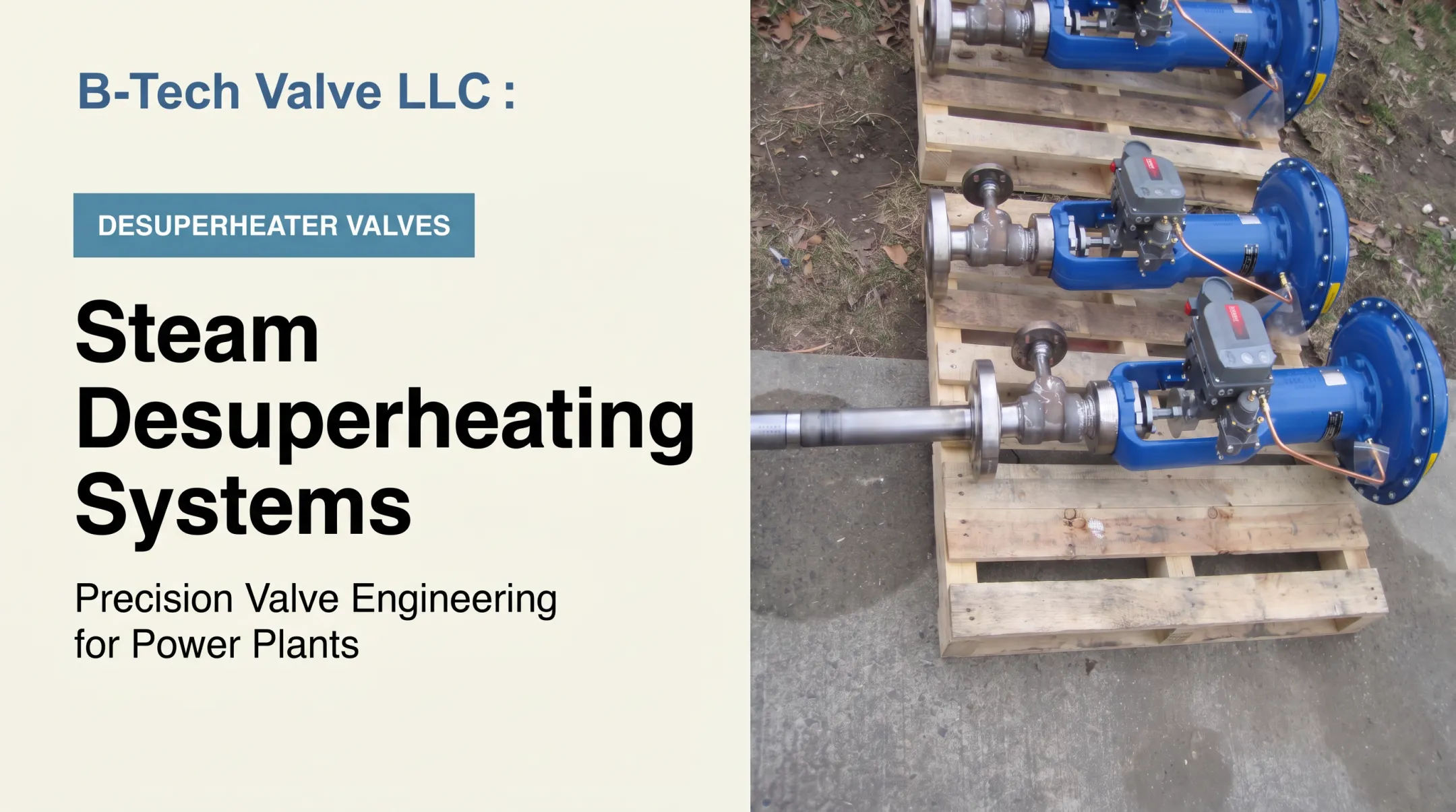
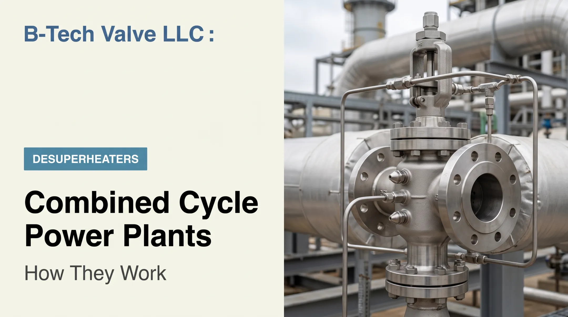
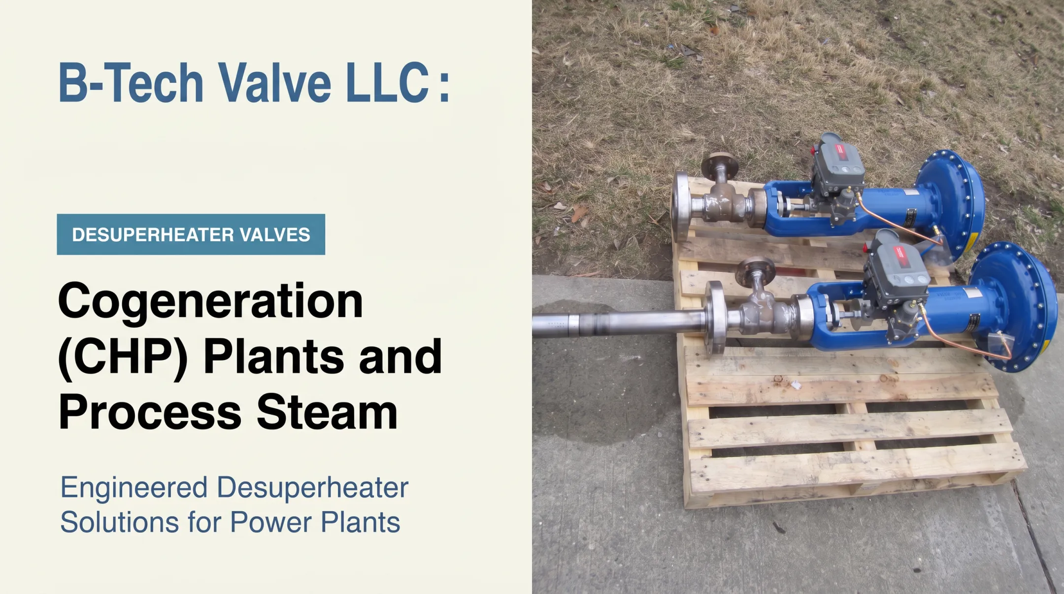
Steam temperature control deserves particular attention. Steam that's too hot or carries unsuitable moisture content can damage downstream piping, steam traps, rotating seals, and steam-turbine internals over time. This is where desuperheater and attemperator valves come into the picture, injecting water spray into steam lines to bring temperatures into a safe operating range.
B-Tech Valve, a US manufacturer based in New Jersey, builds application-sized desuperheater assemblies for this exact role in power and process steam systems (these valves address one function within a much larger control architecture, not the entire plant's instrumentation). Diagrams showing a single desuperheater symbol are simplifications; actual plants rely on separate safety, isolation, relief, bypass, and trip systems to respond to abnormal pressure, temperature, or flow conditions. A basic flow diagram shouldn't be mistaken for a complete safety-instrumented design.
Output, Cooling, and Electrical Integration
Once both generators produce power, that electricity flows through transformers to the plant switchyard and onto the grid when these elements appear on the diagram. Meanwhile, the condenser and cooling system handle the heat rejection side — pulling low-grade heat out of the steam cycle after the steam turbine.
Three cooling arrangements show up most often on diagrams, according to EIA data:
| Cooling Type | How It Works |
|---|---|
| Once-through | Draws water from a nearby source, cools the condenser, returns warmer water to that source |
| Recirculating / closed-loop | Reuses cooling water continuously within closed-loop piping (cooling towers) |
| Dry / air-cooled | Uses ambient air directly, or indirectly through a closed-loop condenser system |
Plant performance ties directly to how well these systems work together. Stable steam conditions, effective heat recovery in the HRSG, adequate cooling capacity, clean heat-transfer surfaces, and coordinated control across both cycles all influence the final output a diagram represents.
Where Are Combined Cycle Power Plants Used?
US utilities and independent power producers rely heavily on combined-cycle plants for base and intermediate load generation. The two-stage energy conversion process lets a single gas-fired power block deliver substantial, sustained output, which explains why this technology makes up such a large share of national gas-fired capacity.
Industrial and CHP applications look a bit different. Facilities that need both electricity and usable process steam, such as refineries, chemical plants, and paper mills, often adjust the basic combined-cycle layout.
The EPA's CHP Partnership describes combustion-turbine systems feeding unfired HRSGs that supply process steam directly to facility operations. In these setups, not all recovered heat is routed through a steam turbine for additional electricity. Plant design depends heavily on:
- Electrical demand relative to steam demand
- Process-steam temperature and pressure requirements
- Expected operating profile (continuous versus intermittent)
Combined-cycle versus simple-cycle selection generally comes down to priorities. Combined-cycle plants tend to prioritize fuel utilization and sustained generation. Simple-cycle plants, which skip the steam-turbine bottoming cycle entirely, often get selected for simpler equipment, faster startup, or peaking service. That said, actual project selection depends on site-specific requirements, fuel costs, and grid needs. There's no absolute rule that fits every situation.

Conclusion
The logic behind a combined cycle power plant diagram comes down to one sequence: the gas turbine generates the first block of power, and the HRSG recovers exhaust heat that would otherwise escape up the stack. The steam turbine then converts that recovered heat into a second block of electricity before the steam condenses and recirculates.
That flow shapes real engineering, maintenance, and procurement decisions. It matters most around steam-temperature control, where replacement components need to match actual line conditions, pressure, temperature, flow, and plant configuration rather than generic specifications.
If you're evaluating steam-conditioning equipment for a combined cycle application, B-Tech Valve's application engineering team can help with sizing and replacement guidance based on your specific system.
Frequently Asked Questions
How does a combined cycle power plant work?
A gas turbine burns fuel to generate electricity directly, then its exhaust heat produces steam in an HRSG. That steam drives a second turbine for additional electricity before condensing and recirculating.
What are the main components of a combined cycle power plant?
Core components include the gas turbine, generator, HRSG, steam turbine, condenser, feedwater pumps, cooling system, control systems, electrical equipment, and connecting piping. Specific layouts vary by manufacturer and configuration.
What does the HRSG do in a combined cycle power plant?
The HRSG captures heat from gas-turbine exhaust and transfers it to feedwater, converting that water into steam. This steam then drives the steam turbine for additional power generation.
What is the difference between a simple-cycle and combined-cycle power plant?
A simple-cycle plant generates electricity through the gas turbine alone, venting exhaust heat to the atmosphere. A combined-cycle plant recovers that exhaust heat through an HRSG to run a second steam-turbine cycle.
Why is a combined cycle power plant more efficient?
It recovers thermal energy a simple-cycle plant would otherwise reject as waste heat. 2024 EIA data shows average tested heat rates of 7,548 Btu/kWh for combined-cycle units versus 10,999 Btu/kWh for simple-cycle gas turbines . Lower heat rates mean better fuel efficiency.
What do the arrows in a combined cycle power plant diagram represent?
Arrows show the direction of flow for air, fuel, combustion gas, water, steam, cooling medium, exhaust, and electrical output as they move through connected plant systems.