This guide is written for power plants, HRSGs, boiler and cogeneration operators, refineries, chemical facilities, pulp and paper plants, EPC engineers, maintenance teams, and valve distributors across the US. Sizing matters because it determines whether outlet temperature stays stable, heat transfer performs as designed, and downstream piping, traps, and rotating equipment stay protected from water carryover, excess pressure loss, noise, or vibration.
We'll walk through sizing the steam control valve, sizing the spray-water path, and validating the complete desuperheater installation as three separate but connected engineering tasks.
Key Takeaways
- Size valves from process conditions and required Cv, not nominal pipe size
- Steam sizing depends on mass flow, pressure, and temperature; spray water adds water pressure, atomization, and evaporation distance
- Check maximum, normal, and minimum cases for capacity, noise, cavitation, and actuator needs
- Treat rules of thumb as a screening step, not a substitute for verified calculations
What Is Control Valve Sizing for Steam and Spray Water?
Control valve sizing means selecting a valve capacity that passes the required flow while holding stable control across the full operating range, not just at one design point. Manufacturers rate that capacity using a flow coefficient, either Cv (US customary units) or Kv (metric), and the two scale together under a fixed conversion factor.
Always confirm which coefficient a manufacturer's data sheet uses before comparing products. This guide uses Cv throughout, consistent with US plant practice.
Spray-water injection exists to pull superheated steam temperature down toward a target, typically closer to saturation. For that to work, the injected water has to atomize into fine droplets, evaporate fully inside the pipe, and never reach downstream equipment as liquid.
A valve or nozzle that injects the correct total flow can still cause thermal shock, wet steam, or piping damage if atomization is poor.
Why a Valve That Fits the Pipe Still Needs Sizing
Line size is a mechanical constraint, not a sizing answer. Confusing the two is one of the most common mistakes in steam-conditioning projects. Control-valve sizing is also distinct from:
- Line sizing – sets pipe diameter for velocity and pressure-drop limits, not valve capacity
- Pressure-reducing valve selection – focuses on pressure letdown, not temperature control
- Desuperheater selection – covers the water-injection hardware and geometry, separate from the valve trim itself
A valve that bolts neatly into the line can still be oversized, undersized, unstable at low load, or simply the wrong trim for the service.
Steam Side vs. Water Side
Steam is compressible. As pressure drop across the valve increases, steam velocity through the trim can reach sonic conditions and the flow becomes choked. Additional pressure drop then no longer increases flow.
Spray water is a liquid, so the sizing question shifts to pressure drop, velocity, and whether the water will flash or cavitate before it reaches the nozzle. Each side needs its own calculation, verified separately rather than assumed from the other.
How the Sizing Process Works
Start with a complete design basis before running any calculation. Gather:
- Minimum, normal, and maximum steam mass flow
- Inlet pressure and temperature, plus downstream pressure
- Target outlet temperature and allowable pressure drop
- Spray-water pressure, temperature, and quality
- Line size, control range, and the location of the downstream temperature sensor
Missing even one of these numbers forces assumptions into the calculation, and assumptions are where sizing errors start.
Calculating Steam-Valve Capacity
Steam sizing uses a compressible-flow method, not a liquid equation. The ANSI/ISA-75.01.01 standard calculates required Cv from the pressure ratio across the valve, the choked-pressure ratio, a specific-heat-ratio factor, steam temperature, and mass flow.
Upstream and downstream pressure both matter, not just the differential. Their ratio determines whether the valve runs in normal flow or choked flow. Identify which condition applies for every operating case before finalizing Cv.
Determining Spray-Water Demand
Spray-water flow comes from a heat balance, not a fixed percentage of steam flow. Spirax Sarco's desuperheating guidance frames this as an enthalpy balance: steam mass flow and inlet enthalpy, target outlet enthalpy, and the enthalpy of the incoming water set how much water the system needs at each load point.
Run this calculation at minimum, normal, and maximum load. The water demand curve rarely scales in a straight line with steam flow.
Sizing the Spray-Water Valve and Hardware
Once the water quantity is known, size the valve and injection hardware together:
- Confirm available water pressure clears downstream steam pressure by enough margin for the desuperheater type
- Check liquid velocity, flashing, and cavitation risk at the valve trim
- Verify valve rangeability covers minimum through maximum water flow
- Confirm nozzle or spray-ring capacity matches the valve's flow range
- Assess whether the arrangement delivers fine enough atomization for full evaporation
Validating the Complete Installation
Don't stop at the first calculated Cv. Check these factors across every case, including start-up and shutdown:
- Valve travel and minimum controllable flow
- Actuator and positioner response
- Steam velocity, noise, and vibration
- Thermal stress and evaporation distance
- Sensor response
In practice, this breaks down into three steps:
- Gather and verify process data from the P&ID, equipment data sheets, and operating history. Flag inconsistent values before calculating anything.
- Calculate steam and spray-water capacity separately, then compare both results against the manufacturer's Cv, nozzle, spray-ring, and pressure-class data.
- Review the assembly across every operating case (start-up, minimum, normal, maximum, upset, and future growth) and document the assumptions behind the final selection.

Where Steam and Spray-Water Sizing Is Applied
Steam and spray-water sizing shows up anywhere superheated steam temperature needs active control:
- Main steam temperature control at the boiler or HRSG outlet
- Superheater and reheater outlet attemperation
- Turbine bypass systems
- Pressure-reducing stations paired with downstream desuperheating
- Process steam lines feeding heat-transfer equipment
Re-sizing usually gets triggered by a specific event, not a routine review. Common triggers include:
- A new plant, process line, or boiler duty change
- Replacement during a planned outage
- Increased production or altered steam conditions
- Recurring high-outlet-temperature alarms or water carryover
- Unstable control or an obsolete desuperheater design
Start-up and low-load conditions are often harder to control than the normal design point. At low steam flow, there's less mass available to absorb and carry the injected water. The same spray valve that performs well at full load can struggle to deliver a small, well-atomized flow at 20% load.
Recurring modulating service, where the valve works continuously across a wide range, deserves more scrutiny than a one-time commissioning or emergency bypass application that only operates occasionally.
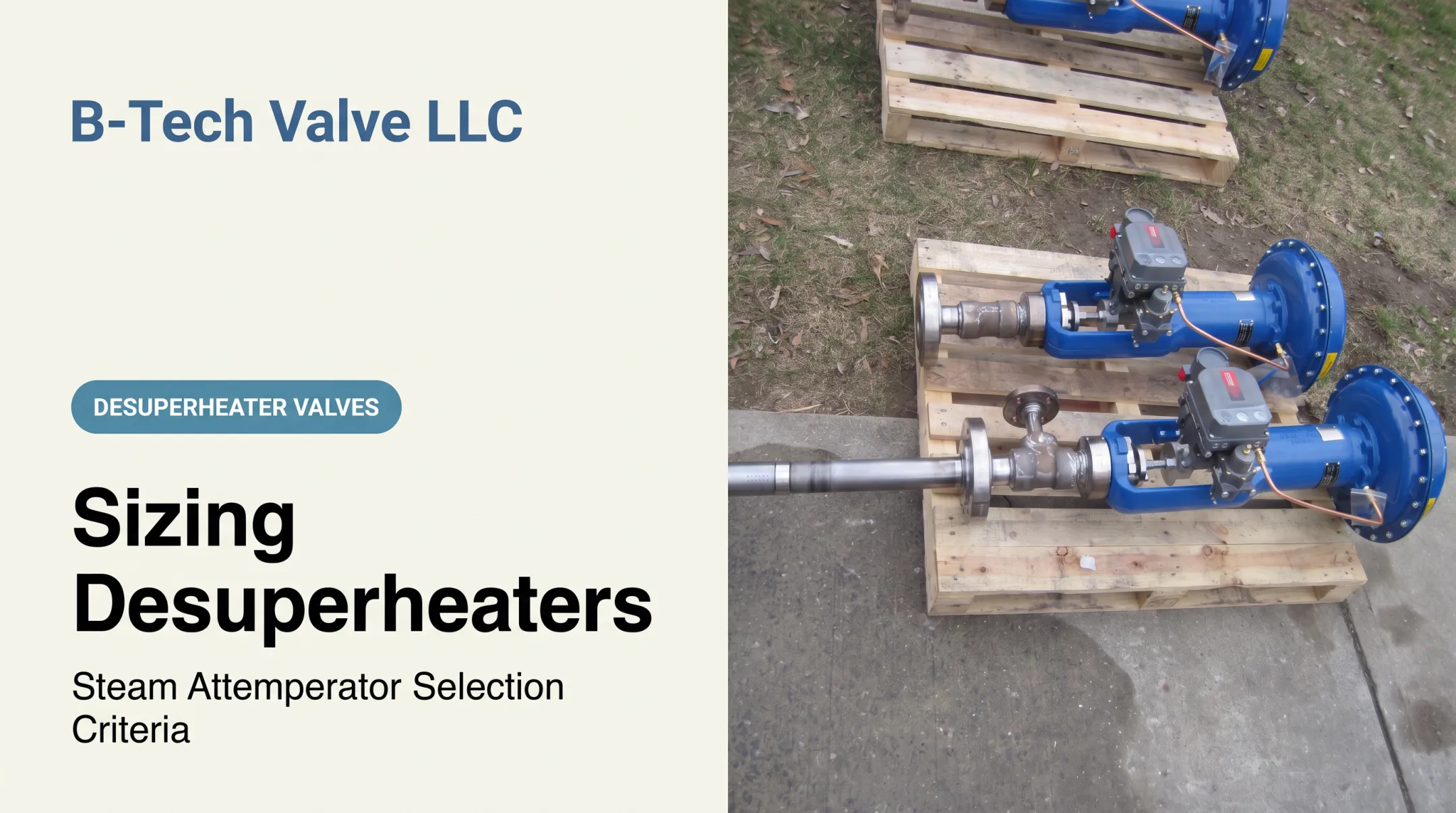
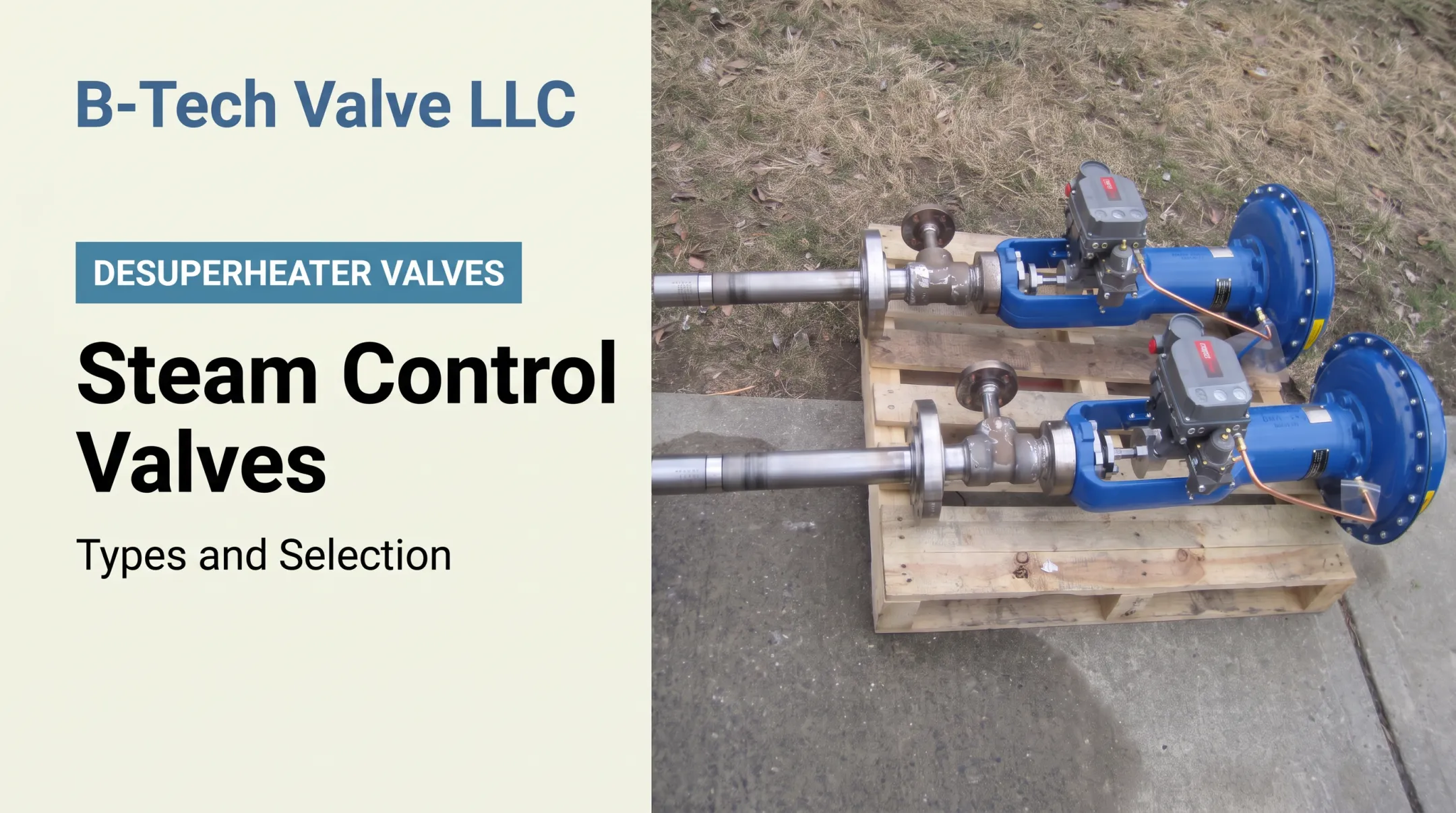
This is where product selection starts to matter. B-Tech Valve's LPD design is built for steam pipes 6 inches and larger, combining a variable-nozzle control valve and desuperheater in one actuated assembly.
The SPAD spray-ring design serves 4-inch and smaller lines, pairing a fixed-nozzle spray ring with a separate temperature-control valve. Either option still needs application-specific sizing and review before specification.

Key Factors That Affect Sizing
Five categories of factors shape the final valve and desuperheater selection.
Process inputs:
- Minimum, normal, and maximum steam mass flow
- Inlet and outlet pressure, plus inlet superheat
- Target outlet temperature
- Spray-water pressure, temperature, and quality
- Allowable pressure drop across the valve
Control-performance requirements:
- Required turndown and minimum controllable flow
- Expected valve travel and rangeability
- Control-loop response time and sensor location
- Whether a single valve or staged arrangement fits the load range
Compressible-flow and pressure effects:
- Whether steam or water flow could become choked at the design pressure ratio
- Pressure recovery, flashing, and cavitation risk
- Noise and vibration, using recognized valve noise-prediction methods rather than a nominal Cv guess
- Downstream velocity, not just nominal Cv
Installation geometry and evaporation:
- Pipe diameter, injection orientation, and nozzle or spray-ring arrangement
- Straight-run and mixing-length requirements
- Downstream elbows, fittings, and temperature-sensor placement
- Drain points and the risk of unevaporated water settling in low spots
Mechanical and safety constraints:
- Body and trim materials matched to pressure class and temperature
- Actuator force, fail-safe position, and control-air or electrical supply
- Thermal expansion and inspection access
- Compliance with ASME B16.34 ratings and applicable plant standards
Treat manufacturer-specific guidelines as a starting point, not a universal rule. Pressure-class ratings, noise limits, and sizing coefficients should trace back to the applicable standard or the selected manufacturer's certified data.
Common Sizing Errors and When a Standard Approach May Not Be Appropriate
Mistakes That Show Up Again and Again
The most frequent sizing errors are easy to spot in hindsight:
- Matching valve size to pipe diameter instead of calculated Cv
- Sizing from a single operating point instead of min/normal/max cases
- Adding an oversized safety margin without verifying its effect on turndown
- Confusing pressure-reducing service with temperature control
- Ignoring available spray-water pressure
- Assuming injected water will evaporate regardless of line layout
Symptoms of a Poorly Sized System
Poor sizing or application tends to announce itself:
- Valve stays nearly closed or fully open most of the time
- Unstable outlet temperature or excessive cycling
- Poor control at low load
- High noise, vibration, cavitation, or flashing damage
- Wet steam, downstream thermal shock, or corrosion
- Damage to seals, steam traps, piping, or rotating equipment
A 2009 Combined Cycle Journal assessment of 11 HRSG plants found that in 9 of them, the spray-water arrangement could allow unvaporized water into downstream piping during low or zero steam flow. The same assessment described severe thermomechanical fatigue when that water hit hot piping.

That's a sample from real plants, not a universal failure rate, but it shows why evaporation distance deserves as much attention as flow capacity.
A larger Cv doesn't automatically mean better control. It often means less usable travel and worse resolution at low load.
Higher water pressure doesn't guarantee good atomization either; nozzle design and droplet size matter more than pressure alone. A heat balance that checks out on paper also doesn't prove the hardware has enough evaporation distance downstream.
When to Look Beyond a Standard Single-Valve Design
A standard single-valve, single-nozzle approach may not fit:
- Very wide turndown requirements
- Rapidly changing loads
- Limited available water pressure
- High pressure ratios or short downstream mixing distance
- Severe noise or cavitation risk
- Dirty or contaminated water, or two-phase flow
- Critical turbine-bypass service
In these cases, staged injection, specialized trim, multi-nozzle or steam-atomizing designs, or a detailed manufacturer review usually serve better than forcing a standard assembly to cover a range it wasn't built for. Rules of thumb work for preliminary screening; final selection still needs verified calculations, plant specifications, and the manufacturer's certified performance data.
Conclusion
Reliable steam and spray-water sizing takes a coordinated review of flow capacity, pressure drop, temperature reduction, controllability, atomization, evaporation, materials, and installation geometry. It is not a single calculation.
Line size tells you what fits in the pipe. It says nothing about how well the valve will control at 20% load during start-up or handle an upset case five years from now.
Before specifying a replacement or new desuperheater, pull together the full process data sheet covering every operating case, not just the design point. Have an application engineer review it.
B-Tech Valve's LPD and SPAD assemblies are built around that kind of project-specific sizing. Neither is a drop-in answer without reviewing your actual steam and water conditions first. Request a sizing data sheet and talk through the application before ordering anything.
Frequently Asked Questions
What are the rules of thumb for sizing control valves?
Rules of thumb help with a quick check on valve travel, minimum controllable flow, pressure drop, and line-size relationship. For steam and spray-water service, still run verified calculations for capacity, choked flow, noise, cavitation, actuator sizing, and evaporation.
How do you calculate the required Cv for a steam control valve?
Use steam mass flow, upstream and downstream pressure, and steam temperature or fluid properties in the standard compressible-flow equation or a manufacturer's sizing tool. Check every operating case, not just the normal design point.
How is spray-water flow calculated for a desuperheater?
Spray-water demand comes from a heat and mass balance using steam flow, inlet and target outlet conditions, and the water's inlet enthalpy or temperature. Once you have the flow number, check it against atomization and complete-evaporation requirements.
Should a steam control valve be the same size as the steam pipe?
No. Nominal pipe size doesn't determine control-valve size. The valve has to meet capacity, controllability, velocity, noise, and pressure-class requirements while still fitting the line connections.
What information is needed to size a desuperheater?
Provide min, normal, and max steam flow, pressures, temperatures, target outlet temperature, and spray-water conditions. Also include line size, allowable pressure drop, turndown, downstream geometry, sensor location, materials, and control philosophy.
What happens if a desuperheater or control valve is oversized?
Excess capacity reduces usable valve travel, increases sensitivity and cycling, and makes stable temperature control harder, while adding unnecessary cost. An oversized spray-water path can make low-load injection especially difficult to control.