In US power plants, refineries, chemical facilities, and manufacturing sites, actuator selection touches flow control, process stability, equipment protection, safety, energy use, and maintenance budgets all at once. Many engineers default to whatever power source is already on-site without checking whether it actually fits the application.
This article compares pneumatic, electric, and hydraulic actuators, covers linear versus rotary movement and spring-return versus double-acting configurations, and walks through the criteria that determine the right fit for your process.
Key Takeaways
- A control valve actuator moves a valve in response to a signal so the process can regulate, start, stop, or isolate flow
- Pneumatic, electric, and hydraulic actuators differ in available utilities, speed, force, precision, and fail-safe behavior
- Actuator output movement (linear or rotary) must match the valve design it's paired with
- Spring-return and double-acting setups respond differently when power or air is lost
- Proper selection depends on thrust/torque data, modulation needs, environment, and lifecycle costs
What Is a Control Valve Actuator?
A control valve actuator is the mechanical device that receives a signal from the control system and moves the valve's closure element, whether a plug, disc, or ball, to the commanded position. It's the muscle behind the instruction.
The basic sequence works like this: a controller compares the desired process condition against measured feedback, sends a signal, and the actuator converts pneumatic pressure, hydraulic pressure, or electrical energy into mechanical movement at the valve.

Actuator vs. Valve vs. Positioner
These terms get mixed up constantly, so here's the breakdown:
- The control valve regulates the process fluid itself
- The actuator supplies the force and movement
- A positioner refines that movement by comparing commanded position to actual position
- A solenoid, converter, or control module may ride along in the package, but none of these replaces for the actuator
Linear vs. Rotary Movement
Actuators fall into two movement categories, and this distinction drives nearly every downstream decision:
- Linear actuators move a stem in a straight line, typically paired with globe, gate, diaphragm, and other rising-stem valves
- Rotary actuators produce quarter-turn or multi-turn rotation, typically paired with ball, butterfly, and plug valves
Modulating vs. On/Off Service
Modulating control valves need more from an actuator than simple on/off valves. On/off service only needs the actuator to reach two endpoints reliably. Modulating service demands stable, repeatable positioning anywhere across the full travel range, not just at the stops.
Why Control Valve Actuators Matter in Industrial Process Control
Actuator performance directly determines whether a plant holds pressure, temperature, flow, and level inside the range the process needs. When the actuator underperforms, the whole loop suffers.
A poorly sized or mismatched actuator can cause several problems at once:
- Incomplete stroke, where the valve never reaches full travel
- Unstable control or hunting behavior
- Slow response during upset conditions
- Seat leakage from inadequate shutoff force
- Excessive wear on packing, seats, and stem
- Failure to reach the required fail-safe position on loss of signal
Actuators also do the work humans shouldn't have to. In hazardous atmospheres, remote pipeline stations, high-temperature steam lines, or anywhere manual operation would be unsafe or impractical, the actuator stands in for a person turning a handwheel.
Friction is one of the biggest hidden enemies of accurate control. Fisher's Control Valve Handbook notes that for the best reduction in process variability, total deadband across the entire valve assembly should stay at 1% or less. That's a tight tolerance, and it's part of why positioners exist.
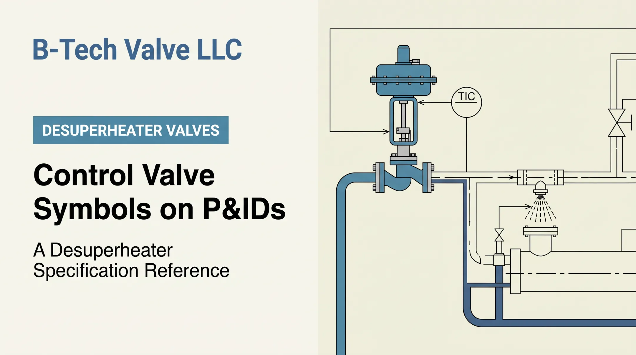
Positioners and feedback devices become necessary when changing differential pressure, valve friction, high closing force, or precise modulation requirements push beyond what the actuator alone can deliver accurately. A positioner compares commanded position to actual stem or shaft position and corrects the error in real time.
Pneumatic Control Valve Actuators
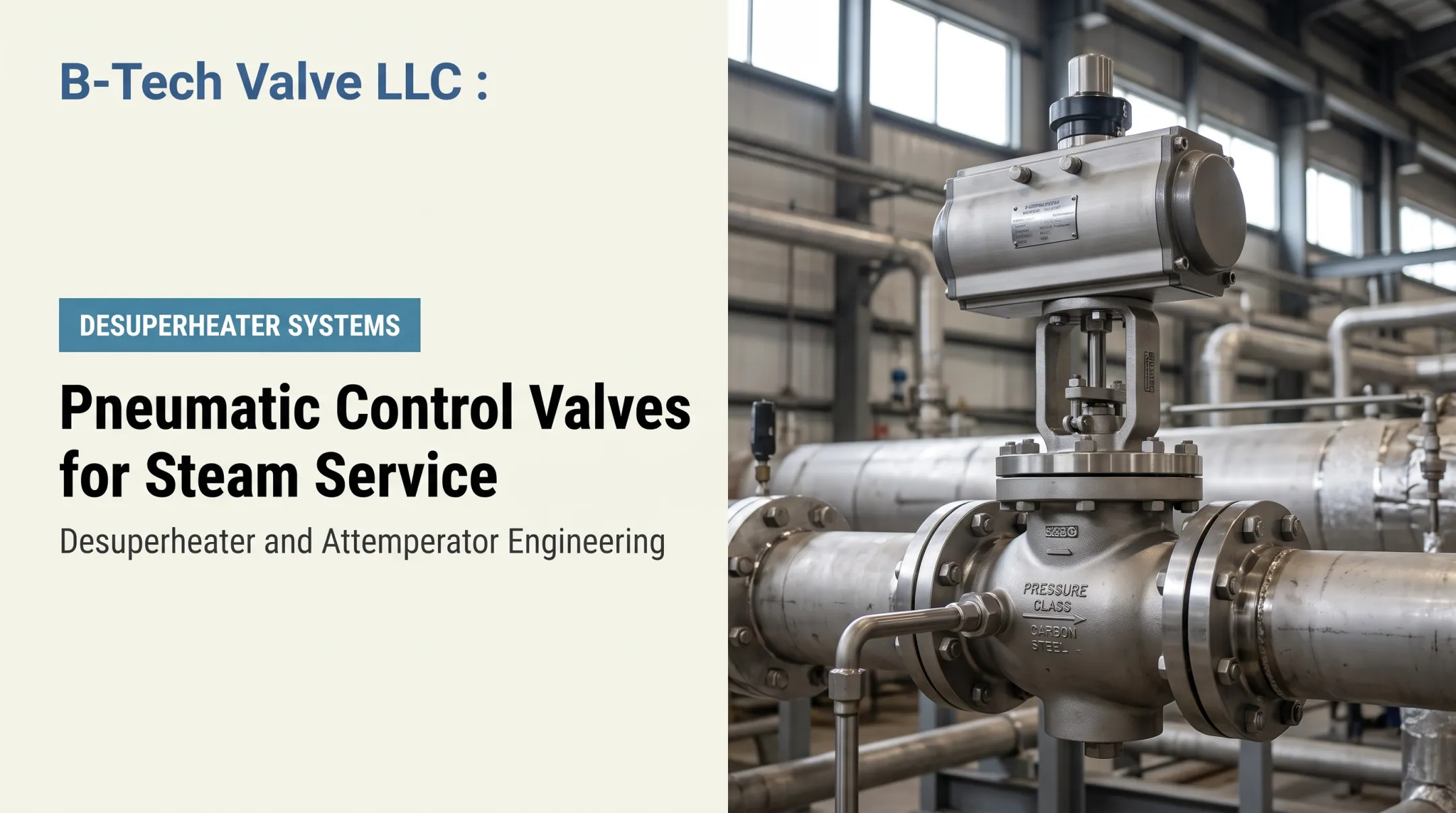
Pneumatic actuators use compressed instrument air acting on a diaphragm or piston to generate linear thrust or rotary torque.
Diaphragm-style units use air pressure against a flexible diaphragm connected to the stem. Piston-style units use air against a rigid piston, which generally delivers higher thrust and faster stroking in a more compact footprint.
Spring-Return vs. Double-Acting
These two configurations behave very differently when the air supply fails:
- Spring-return actuators use air for one direction and a spring for the return. Lose air pressure, and the spring drives the valve to a defined fail-open or fail-closed position.
- Double-acting actuators use air for both directions. Lose air, and the valve generally stays put, unless a trip valve or lock-up accessory has been added for a defined fail-safe response.
Strengths and Trade-Offs
Pneumatic actuators tend to suit applications with fast response needs, frequent cycling, hazardous locations, and plants that already run a clean, dry instrument-air system.

Strengths include:
- Rapid stroke speed
- Decades of control-system integration
- High available force in a properly sized package
Those benefits come with real constraints:
- Dependence on compressor capacity and air quality
- Potential leakage through fittings and seals over time
- Added need for positioners or volume boosters in demanding modulating service
- Overall reliability tied directly to instrument-air system uptime
Rotary Torque Curves
Rack-and-pinion and scotch-yoke mechanisms produce different torque curves across the stroke:
- Scotch-yoke designs typically deliver higher starting torque for valves with high seating loads
- Rack-and-pinion units often provide more consistent torque throughout travel
Always verify actual torque output against the valve manufacturer's requirements at every point in the stroke, not just at the endpoints.
Electric Control Valve Actuators
Electric actuators pair a motor, gearing, limit devices, and control electronics to convert electrical energy into linear or rotary valve movement. Two service types exist here, and they're not interchangeable:
- Basic motor-drive actuators handle open-stop-close service, moving the valve between two fixed endpoints
- Modulating electric actuators accept a proportional control signal and position the valve anywhere between travel limits
Where Electric Actuators Make Sense
Electric actuators often get the nod in locations without instrument air, installations built around electronic control architecture, or sites where running conduit is simpler than installing air tubing. B-Tech Valve's LPD large-pipe desuperheater, for example, is available with an electric actuator package driving its variable-nozzle control valve, which gives plants flexibility when compressed air isn't the preferred utility.
Selection Factors That Matter
Before specifying an electric actuator, confirm:
- Voltage, motor sizing, and travel speed for the application
- Duty cycle rating against expected cycling frequency
- Enclosure rating and hazardous-location certification
- Manual override availability for power-loss situations
- Protection from moisture, dust, and corrosive atmospheres
Duty cycle deserves extra attention. Rotork's IQT3 Pro part-turn actuator, for instance, is rated for up to 1,200 starts per hour in S2/S3 duty service, a reminder that cycling frequency and motor heating need to be matched against the actual service profile, not assumed.
Limitations to Watch
Electric actuators can run into speed constraints on fast-acting applications, motor heating during frequent cycling, and electrical installation requirements that add cost in classified areas. Critically, don't assume loss of electrical power produces a safe valve position by default; verify the actual fail behavior with the manufacturer.
Enclosure and area classification requirements, including NEMA and IP ratings, need to be confirmed against documented certifications for the specific actuator model and the site's hazardous-area classification.
Hydraulic Control Valve Actuators
Hydraulic actuators use pressurized liquid to generate force or torque, available in linear, rotary, spring-return, and double-acting arrangements. Because hydraulic fluid is far less compressible than air, these actuators deliver high force and compact power density. That makes them relevant for large valves, high differential pressures, remote installations, and specialized heavy-duty service.
Hydraulic vs. Pneumatic Systems
The core difference comes down to fluid behavior and system complexity:
- Hydraulic fluid barely compresses, enabling precise, forceful movement
- Pneumatic systems are simpler to install and maintain overall
- Hydraulic installations require a power unit, reservoir, filtration, hoses, and leak control
- Added hardware raises system complexity and maintenance scope
Trade-Offs to Consider
Hydraulic actuators aren't the default choice for ordinary control valves. Consider them when required thrust or torque exceeds what a practical pneumatic or electric package can deliver. Confirm that need against manufacturer sizing data rather than assuming it. Watch for:
- Slower or more complex response in some system designs
- Fluid maintenance and contamination risks
- Leak potential at hoses, fittings, and seals
- Temperature sensitivity affecting fluid viscosity
- The need for a well-maintained hydraulic power unit
Specialized arrangements like electrohydraulic actuators or gas-over-oil systems serve specific applications, such as emergency shutdown valves or remote pipeline stations. These remain application-specific solutions, not default options for routine control valve service.

How to Choose the Right Control Valve Actuator
The right actuator depends on more than power source. Valve type, process conditions, available utilities, safety requirements, and lifecycle objectives all have to line up.
Purpose and Valve Compatibility
Start here:
- Confirm whether the valve needs linear, quarter-turn, or multi-turn movement
- Verify the actuator's stroke, rotation, mounting, and coupling match the valve exactly
- Establish whether the service is on/off, throttling, emergency shutdown, or regulation
Force, Torque, and Operating Conditions
Collect the real numbers before specifying anything:
- Valve size, pressure class, fluid type, and temperature
- Upstream and downstream pressure, plus differential pressure
- Shutoff requirement, friction, and required seating force
Use the valve manufacturer's sizing tables to verify available thrust or torque across the complete stroke, including startup and worst-case conditions, not just the nominal operating point.
Failure Behavior and Control Accuracy
Decide upfront whether the valve must fail open, fail closed, fail in place, or move to another defined safe state on loss of air, hydraulic pressure, electrical power, or signal.
Then determine whether a positioner, feedback sensor, booster, solenoid, or digital communication capability is needed for repeatable modulation.
Utilities, Environment, and Total Cost
Compare the availability and cost of instrument air, hydraulic power, and electrical service, including backup supply where it's required. Check ambient temperature, moisture, dust, vibration, corrosion exposure, hazardous-area classification, and accessibility for inspection.
Then look past the purchase price. Factor in installation, calibration, spare parts, energy consumption, outage exposure, and replacement lead time.

Before finalizing anything, run a quick sanity check:
- Confirm force, torque, travel, speed, and fail behavior match the valve and process before choosing on familiarity or upfront price
- Treat power source (pneumatic, electric, hydraulic) and movement type (linear, rotary, spring-return, double-acting) as separate decisions
- Include accessories such as position feedback, air quality control, and electrical protection
- Require a documented sizing review covering process conditions, valve data, actuator output, utility needs, failure mode, and certifications
For steam-conditioning and desuperheating applications, an application engineer should review line size, steam conditions, spray-water requirements, pressure class, and control objectives before the valve and actuator package is specified.
B-Tech Valve LLC works this way as a US manufacturer, sizing probe-type, variable-nozzle desuperheater and attemperator valve assemblies for each customer's application. Pressure classes run from ASME B16.34 Class 150 through 2700, with ratings up to 1,200°F. Products are stocked, with final assembly and testing handled in-house for faster turnaround on outages and upgrades.
Conclusion
A control valve actuator is the link between a process control signal and the physical movement of a valve. Getting the selection right shapes control quality, safety, reliability, and long-term maintenance cost.
Pneumatic, electric, and hydraulic actuators each serve real use cases. The final choice comes down to movement type, action mode, fail position, sizing against real process data, and environmental conditions, not simply whichever power source happens to be convenient.
Before specifying an actuator for a critical steam or process installation, pull complete process and valve data together and involve an experienced application engineer. Getting the sizing review right the first time costs far less than replacing a mismatched actuator mid-outage.
Frequently Asked Questions
What is the typical cost of replacing a valve actuator?
Replacement cost varies with the actuator's power source, size, force or torque rating, controls, hazardous-area requirements, installation labor, and whether the valve itself also needs replacement. Get an application-specific quote rather than relying on a generic price range.
How does an actuator valve work?
A control signal causes the actuator to convert air pressure, hydraulic pressure, or electrical energy into linear or rotary movement, which then positions the valve to regulate or isolate flow. The exact mechanism depends on the actuator type and configuration.
What does a valve actuator do?
The actuator supplies the force and movement needed to open, close, or modulate a valve, letting the control system operate it remotely and respond to changing process conditions without manual intervention.
Do all control valves have actuators?
Automated control valves require actuators, but some manually operated or self-acting valves use handwheels, levers, gears, springs, or process pressure instead. Terminology varies somewhat by valve type and control-system design.
What are the two main types of valve actuators?
The two primary movement types are linear and rotary. Actuators are also commonly grouped by power source, such as pneumatic, electric, or hydraulic, which describes a different characteristic entirely.
What are the three types of actuators?
Pneumatic, electric, and hydraulic actuators make up the three major industrial power-source categories. Manual operators and specialized electrohydraulic or gas-powered arrangements also show up in specific applications.