Introduction
Controlled steam flow keeps power plants, HRSGs, refineries, chemical plants, pulp and paper mills, cogeneration systems, and industrial boilers running safely. Get it wrong, and you risk equipment damage, wasted fuel, or a forced outage.
Many engineers use "pneumatic control valve" loosely. It can mean a process valve that uses compressed air to regulate steam, or a directional valve that routes air to a machine actuator. This guide covers the first kind: steam-process control and steam conditioning.
We'll walk through how these valves operate, the common steam-service configurations, what data you need to select one, pneumatic actuation and fail-safe requirements, maintenance basics, and where a desuperheater fits into the picture.
Key Takeaways
- Pneumatic actuation delivers reliable modulating or on/off movement when body, trim, actuator, and positioner are sized as one assembly
- Selection hinges on pressure, temperature, flow range, pressure drop, steam condition, fail position, and downstream limits
- Desuperheating is separate: it injects water to cool steam, while a control valve regulates flow or pressure
- Steam's erosive, high-temperature nature makes trim material and actuator sizing higher-stakes than typical process service
What Is a Pneumatic Control Valve for Steam Service?
A pneumatic control valve is an assembly that uses compressed instrument air to position a plug, disc, or other control element inside a steam line. The goal is to regulate flow, pressure, temperature, or heat transfer at a precise setpoint.
The actuator and the valve body do different jobs. The actuator supplies force and motion in response to an air signal. The body and trim create the actual restriction that throttles steam. Neither part does much good without the other being correctly matched.
This is also where terminology gets confused. A modulating steam control valve throttles process steam continuously. A pneumatic solenoid or directional valve simply switches air to a cylinder or other actuator. That is a completely different job, even though both use compressed air.
Where These Valves Show Up
Steam-service pneumatic control valves typically handle:
- Pressure reduction downstream of boilers or headers
- Heat-exchanger temperature control
- Turbine bypass or auxiliary steam regulation
- Boiler and cogeneration plant steam balancing
- Flow control downstream of pressure-reducing stations
Why Steam Is a Demanding Medium
Steam isn't forgiving. High temperature, high velocity, pressure drop across the trim, erosion, noise, condensate formation, and thermal expansion can all shorten a valve's service life if travel or sizing is off.
Core Assembly Components
Each part of the assembly contributes to safe, repeatable control:
- Body and bonnet: contain pressure and house the trim
- Trim (seat, plug, stem): creates the controlled restriction
- Packing: seals the stem against leakage
- Actuator: converts air signal into stem movement
- Positioner: corrects travel against the input signal
- Air filter regulator: conditions supply air
- Solenoid or limit devices (optional): add interlocks or position feedback
How Pneumatic Steam Control Valves Work
The control loop starts with a transmitter (temperature, pressure, or flow) sending a signal to a controller. The controller output goes to a positioner, which adjusts actuator air pressure. The actuator moves the stem, the stem repositions the trim, and steam flow changes accordingly.

A positioner compares the incoming signal against actual valve position and corrects for friction, packing drag, and process forces. Without one, a valve can stick or drift, especially at partial openings where stiction is most noticeable.
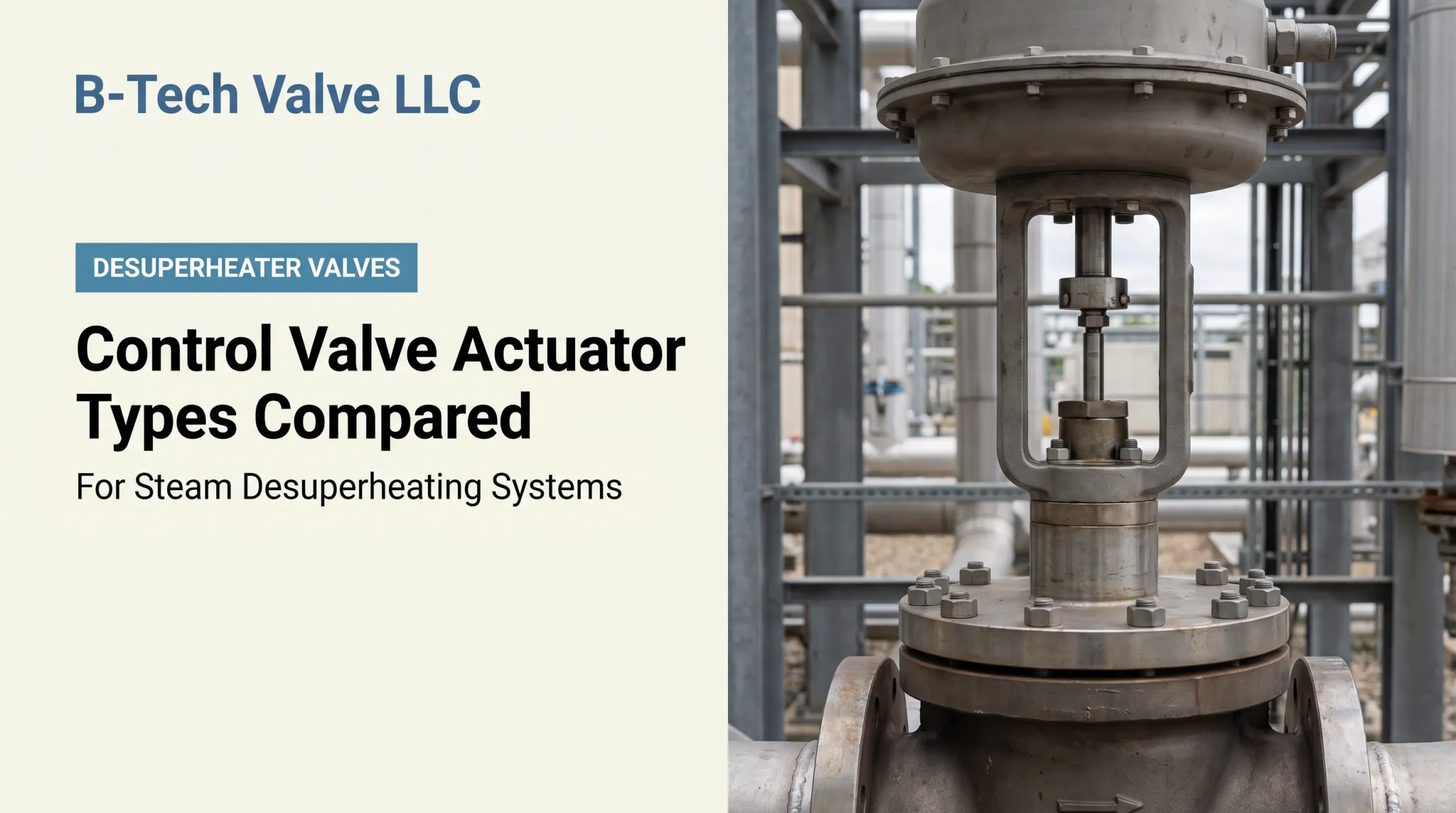
Actuator Types: Diaphragm vs. Piston
| Feature | Diaphragm Actuator | Piston Actuator |
|---|---|---|
| Force output | Moderate | High |
| Typical use | Standard throttling duty | High thrust or long stroke needs |
| Spring return | Common | Available, or double-acting without spring |
| Air pressure needs | Lower | Often higher |
Fisher's 657 and 667 diaphragm actuator literature shows how spring compression and spring rate set the control range, and how stem action (push-down-to-close vs. push-down-to-open) determines the fail state [5]. Piston actuators, such as Fisher's 785C, trade some simplicity for higher thrust across a wider range of travel.
Fail-Safe Action Isn't One-Size-Fits-All
Fail-open, fail-closed, and fail-in-place are actuator spring and valve-action choices, not automatic properties of every pneumatic valve. The correct fail position should come out of your process hazard analysis, not a default assumption. A valve that should stay closed on air loss in one system might need to open in another.
Valve Opening, Pressure Drop, and Control Range
As a valve opens, the relationship between stroke, pressure drop, and steam flow isn't linear. An oversized valve spends most of its life operating near the seat, where control is imprecise. An undersized valve may simply run out of capacity at peak demand. Getting this balance right is the core job of valve sizing.
Steam's Dynamic Challenges
Steam-specific effects to watch for:
- Flashing: when downstream pressure drops below the liquid's vapor pressure, erosive vapor-liquid mixtures can persist downstream
- Water hammer: condensate slugs striking fittings at high velocity, often from low points or rapid cold-start valve opening
- Noise and vibration: compressible-flow noise has a recognized prediction method in aerodynamic noise standards for single-phase gases and vapors
- Erosion: flashing or cavitation-resistant trim designs can extend service life in affected applications
Instrument air must stay clean, dry, and stable. Moisture, oil carryover, or unstable supply pressure cause sluggish movement, stiction, leakage, or an incorrect fail action at the worst possible moment.
Valve Types and Steam-Service Configurations
Not every steam-service valve does the same job, and treating them as interchangeable leads to selection mistakes.
| Configuration | Primary Role | Notes |
|---|---|---|
| Globe-style control valve | Throttling | Most widely used steam process control valve |
| Angle valve | Throttling with self-draining | Suits layouts needing drainage or flow redirection |
| Three-way valve | Mixing or diverting | More common in liquid service than steam |
| Pressure-reducing control valve | Pressure regulation | Pneumatic designs add flexibility over self-acting units for variable demand |
| Integrated desuperheater assembly | Temperature + flow control | Combines spray-water injection with valve control |
When You Need a Desuperheater
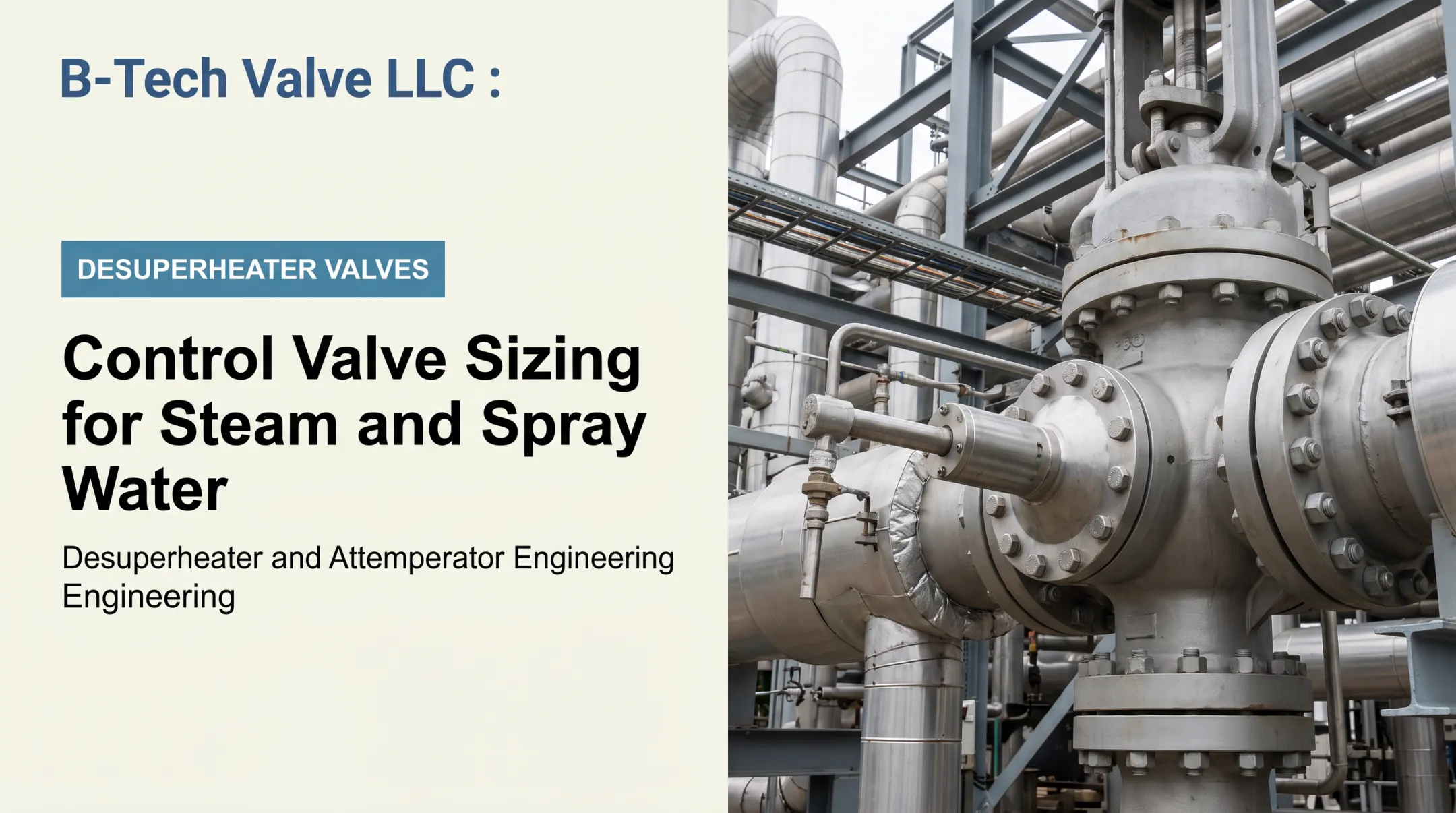
A standard control valve regulates flow or pressure. It doesn't lower steam temperature. If your process needs cooler, saturated, or near-saturated steam for heat transfer or to protect downstream equipment, you need a desuperheater (also called an attemperator) that injects water into the steam stream.

Two Configuration Approaches
B-Tech Valve builds two categories worth understanding as examples of how configuration follows pipe size and application:
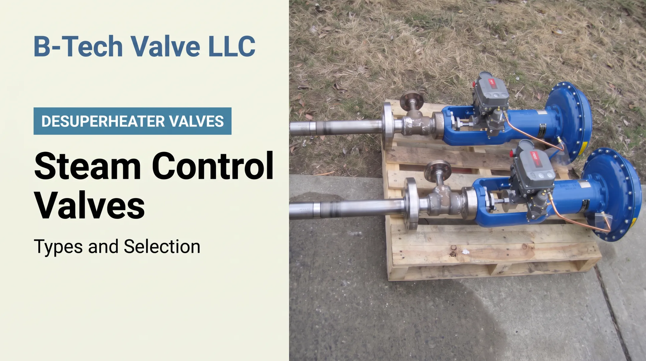
- LPD (Large Pipe Desuperheater): a probe-type, variable-nozzle unit that combines an actuated control valve and desuperheater in one assembly, built for steam lines 6 inches and larger
- SPAD (Small Pipe Attemperator Desuperheater): a fixed-nozzle, spray-ring configuration for steam piping 4 inches and smaller, which receives water from a separate temperature control valve
Always verify current product documentation before relying on dimensional limits. Line size cutoffs and configuration details vary by manufacturer and product revision.
What Determines the Right Configuration
- Line size and pressure class
- Steam temperature and flow range (minimum and maximum)
- Spray water pressure and quality
- Required outlet temperature
- Available straight run and downstream mixing distance
A desuperheater's performance depends on proper atomization, mixing, and residence distance downstream. Don't assume a universal line-size cutoff or a guaranteed outlet temperature applies across all services. Those numbers are application-specific.
How to Select and Specify a Pneumatic Control Valve for Steam Service
Start with a complete specification, not a guess based on the old valve's nameplate.
Specification Checklist
- Steam type (saturated or superheated) and condition
- Pressure and temperature at normal and extreme operating points
- Minimum and maximum flow
- Upstream/downstream pressure and allowable pressure drop
- Line size and connection standard
- Body and trim materials
- Required control range
Define the Primary Duty First
Decide whether the job is throttling, pressure regulation, temperature control, on/off isolation, steam conditioning, or a combined control-and-desuperheating application. This decision shapes every downstream choice, including whether you need a standalone control valve or an integrated desuperheater assembly.
Sizing and Actuator Inputs
Sizing isn't optional math: it determines whether the valve can actually do the job across its full operating range. Key inputs include:
- Flow coefficient (Cv) or equivalent
- Critical or choked flow risk
- Velocity, noise, and cavitation/flashing potential
- Required actuator thrust and shutoff class
- Expected normal operating position (not just min/max)
Formal sizing methodology, such as the equations in the ISA sizing standard, matters because flow capacity calculations change significantly once a valve approaches choked flow conditions. Have sizing confirmed by a qualified valve or process engineer before ordering.
Actuator and Accessory Specifications
- Pneumatic supply pressure and actuator type
- Spring range and fail position
- Positioner signal and feedback type
- Solenoid requirements, if interlocked
- Air filter regulator and volume booster needs
- Lock-up valve and manual override
- Hazardous-area classification and enclosure rating
Material and Trim Decisions
Steam service punishes the wrong material choice. Review body alloy, seat and plug materials, packing compatibility, bolting, erosion resistance, pressure-temperature rating, and thermal cycling tolerance. Pressure and temperature ratings for flanged and welding-end valves typically follow ASME B16.34, which ties allowable ratings to the specific material grade selected.
Documentation to Request
- Dimensional drawings
- Certified sizing calculations
- Material certifications
- Pressure and leakage data
- Installation and calibration instructions
- Spare-parts lists
For replacement or outage work, gather your operating data (pressure, temperature, flow range, and line size) before reaching out. B-Tech Valve reviews process data to evaluate the application; no design or delivery commitment is appropriate before that review happens. Research applicable ASME, ISA, API, and jurisdictional requirements specific to your installation, since no single standard covers every steam system.
Installation, Maintenance, and Troubleshooting
Installation Priorities
- Confirm flow direction before installing
- Support piping independently of the valve body
- Shield the actuator and positioner from excessive heat and vibration
- Install drains or traps where the manufacturer specifies
- Follow upstream/downstream straight-run guidance exactly
Commissioning Checklist
- Verify instrument air is clean, dry, and at stable pressure
- Inspect tubing and fittings for leaks or restrictions
- Stroke the actuator fully and confirm travel matches specification
- Calibrate the positioner against the actual signal range
- Confirm fail action under simulated air loss
- Check packing for leakage and tune the control loop
Common Symptoms and Likely Causes
| Symptom | Likely Source |
|---|---|
| Valve won't move | Instrument air supply or actuator fault |
| Slow response | Positioner tuning or air volume restriction |
| Hunting | Control-loop tuning or oversized trim |
| Internal passing | Trim wear or erosion |
| Excessive noise/vibration | Flashing, cavitation, or choked flow |
Preventive maintenance should include regular air-filter service, calibration checks, packing inspection, and trim inspection during scheduled outages.
Steam systems operate at high energy and temperature. Lockout, isolation, depressurization, and cooling must happen before any inspection, following site-approved procedures and standards such as OSHA's lockout standard for controlling hazardous energy.
Replace the valve or trim when you see:
- Recurring erosion or persistent leakage
- Incorrect fail action
- Unavailable spare parts
- A process change that invalidates the original sizing
Conclusion: Selecting a Reliable Pneumatic Control Valve for Steam
Reliable steam control depends on matching the whole assembly (body, trim, actuator, positioner, accessories, materials, and fail action) to the actual process duty.
A practical decision path looks like this:
- Define the steam condition and control objective
- Collect real operating data across the full range, not just normal conditions
- Evaluate whether desuperheating is required alongside flow or pressure control
- Confirm sizing and safety requirements with a qualified engineer
- Review manufacturer documentation before ordering
- Plan commissioning and maintenance support in advance
B-Tech Valve LLC, based in Palmyra, New Jersey, designs application-sized steam and gas desuperheater and attemperator valves, including the LPD and SPAD product lines. Components come from U.S. machine and fabrication shops, with final assembly and testing done in-house. For outage replacements or new specifications, the team reviews customer process data to size each assembly to the actual application.
Frequently Asked Questions
Are pneumatic controls still used?
Yes. Pneumatic actuation remains common in steam and process applications for reliable fail-safe action, instrument-air compatibility, and use in hazardous or high-temperature environments. It is not automatically best for every application.
What are the two main types of pneumatic control valves?
The classification depends on context. In process control, a pneumatic control valve modulates flow for steam or another medium, while a pneumatic directional or on/off valve routes air to a separate actuator. Define the valve type by its actual application.
How does a pneumatic flow control valve work?
A control signal changes actuator air pressure, which moves the valve trim to regulate flow. Steam-service valves typically add a positioner for accurate travel; small pneumatic circuit flow controls serve an entirely different, machine-level purpose.
What is a pneumatic control valve?
It's an assembly combining a valve body with a pneumatic actuator, positioned by a control signal to regulate steam flow, pressure, temperature, or another process variable.
How do you select a pneumatic control valve for steam service?
Gather steam pressure and temperature, flow range, pressure drop, line size, and materials data. Then define the control objective, required actuator force, fail position, trim selection, positioner, and downstream equipment limits before sizing.
What is the difference between a pneumatic control valve and a desuperheater?
A control valve primarily regulates flow or pressure. A desuperheater injects water to lower steam temperature. Some assemblies, like B-Tech Valve's LPD, combine both functions and require coordinated sizing.