Get it wrong and the consequences show up fast. Undersized piping drives up pressure loss, generates noise and vibration, accelerates erosion, and leaves downstream equipment starved for pressure. Oversized piping wastes material and can actually slow steam velocity enough to encourage condensate pooling.
This article walks through a practical calculator workflow: what inputs to gather, how velocity limits factor in, where saturated steam and condensate piping diverge, and how proper sizing connects to steam-conditioning equipment like desuperheaters.
Key Takeaways
- A sizing calculator supports engineering judgment; it doesn't replace it
- Pipe selection must satisfy velocity and pressure-drop limits simultaneously
- Saturated steam, superheated steam, and condensate lines need different assumptions
- Final sizing always gets checked against applicable codes, specs, and manufacturer data
- Use actual inside diameter, not nominal pipe size, for every velocity calculation
Steam Pipe Sizing Calculator: Required Inputs and Calculation Method
Before opening any calculator, gather your operating data. Guessing at inputs produces a pipe size that looks precise but isn't trustworthy.
Inputs to collect:
- Steam mass flow rate (lb/hr), including normal and maximum load
- Inlet pressure and required outlet/downstream pressure
- Steam temperature, or saturation/superheat condition
- Pipe run length and elevation changes
- Fittings, valves, strainers, and other components in the line
- Desired destination pressure at the end user or equipment
Why Mass Flow Comes First
Mass flow is usually the most reliable starting point because it's what the boiler, turbine, or process actually delivers. The calculator converts mass flow into volumetric flow using steam's specific volume (the inverse of density) at the relevant pressure and temperature.
Steam is compressible, so specific volume changes significantly across pressure ranges, unlike water.
The relationship: volumetric flow = mass flow × specific volume.
From Volumetric Flow to Velocity
Once you have volumetric flow, velocity follows from basic geometry:
- Flow area: A = π × D²/4
- Velocity: u = Q / A
Here's the detail that trips up a lot of sizing exercises: D must be the actual internal diameter, not the nominal pipe size. A 4-inch Schedule 40 pipe doesn't have a 4-inch bore. Using nominal size instead of actual ID can throw off a velocity calculation by 10% or more, and even more for heavier schedules.
Velocity also drives frictional pressure loss along the run. Loss follows the Darcy-Weisbach relationship, scaling with length-to-diameter ratio and velocity squared. ASHRAE's pipe design chapter ties the friction factor to pipe roughness, internal diameter, and Reynolds number.
A solid calculator also adds equivalent-length pressure losses for elbows, tees, reducers, valves, strainers, and control valves. These components often account for more pressure drop than the straight pipe itself.
Worked Example (Illustrative Only)
Say you're sizing a saturated steam line carrying 10,000 lb/hr at 150 psig, targeting a velocity near 8,000 ft/min.
- Specific volume at this pressure is roughly 2.75 ft³/lb
- Volumetric flow = 10,000 × 2.75 = 27,500 ft³/hr, or about 458 ft³/min
- Required area = 458 / 8,000 = 0.057 ft² (about 8.25 in²)
- Solving for diameter gives roughly 3.24 inches of required bore

A 3-inch Schedule 40 pipe (ID 3.068 in) falls short of that bore, which would push velocity above target. Moving up to 4-inch Schedule 40 (ID 4.026 in) gives an actual velocity closer to 5,180 ft/min, comfortably under the limit.
This example is illustrative only. Actual sizing must use your project's verified steam conditions, applicable code requirements, and equipment pressure-loss data, not textbook approximations.
Steam Velocity Limits and Pressure-Drop Checks
Velocity limits exist for a reason, but velocity isn't the only thing that matters. High velocity drives noise, vibration, erosion, water hammer risk, and condensate carryover. Low velocity in condensate-prone lines can let slugs of water form instead of staying entrained.
Recommended vs. Mandatory Limits
Published velocity numbers vary by source and application. They're benchmarks, not universal law.
| Source | Guidance | Context |
|---|---|---|
| ASHRAE's Steam Systems chapter | 6,000–8,000 ft/min at lower pressures; 8,000–10,000 ft/min at higher pressures | Pressure-reduction station context |
| Spirax Sarco guidance | 25–40 m/s (about 5,000–8,000 ft/min) for saturated steam | General rule of thumb |
| Spirax Sarco guidance | 50–70 m/s (about 10,000–14,000 ft/min) for superheated steam, if pressure drop allows | Conditional on available pressure margin |

None of these replace a mandatory limit set by your adopted code, owner specification, or equipment manufacturer. Check those first.
Where Acceptable Velocity Changes
- Main headers: typically sized conservatively since they feed multiple branches
- Branch lines: can run tighter since runs are shorter and losses are more contained
- Control-valve outlets: governed by the valve manufacturer's sizing data, not a generic pipe rule
- Superheated vs. saturated steam: superheated lines tolerate higher velocity since there's no liquid phase to entrain
- Lines with possible condensate carryover: need lower velocity and better drainage, regardless of what a generic chart says
The Larger-Pipe vs. Smaller-Pipe Tradeoff
A bigger pipe lowers velocity and pressure drop but costs more in material, fittings, and support steel. A smaller pipe costs less upfront but risks excess velocity, higher pressure loss, and a line that can't meet destination pressure under full load.
There's no universal rule here: it's a project-by-project balance between capital cost and operating margin.
Equivalent Length Changes the Math
Straight-pipe pressure drop can look perfectly acceptable, right up until you add up every elbow, tee, strainer, and control valve.
Total equivalent length (straight pipe plus the fitting equivalents) is what actually determines the pressure left at the end user. Skipping this step is one of the most common sizing mistakes.
Final Verification Checklist
Before signing off on a pipe size, confirm:
- Design flow rate and velocity are both within limits
- Minimum pressure at the destination is met, not just at the source
- Maximum velocity doesn't exceed application-specific limits
- Operating temperature matches material and pressure-class ratings
- Pipe material and schedule suit the pressure class
- Transient and startup conditions don't exceed steady-state assumptions
Cross-check everything against ASME's Power Piping standard, project specifications, and equipment manufacturer documentation before finalizing.
Step-by-Step Steam Pipe Sizing Workflow
A repeatable process keeps sizing decisions consistent across a project.
- Define the service and operating envelope. Saturated or superheated? Normal and maximum flow? Pressure and temperature range? Startup and low-load conditions matter here too.
- Establish the pressure budget. Identify available inlet pressure, required destination pressure, and losses through valves, strainers, desuperheaters, and heat exchangers along the way.
- Run the calculator for candidate diameters. Use correct steam properties and pipe roughness assumptions; record velocity, friction loss, and outlet pressure for each candidate.
- Select the nearest standard nominal size. Repeat the calculation using actual inside diameter, wall thickness, schedule, and real fitting counts.
- Check all operating points. Design, normal, minimum, and maximum flow all need to pass. A pipe that only works at one flow condition isn't properly sized.
- Review installation details. Slope, drip legs, steam traps, separators, insulation, thermal expansion, and startup condensate management all affect whether the calculated size performs in the field.

Quick Engineer Review Checklist
Before approving a size, verify:
- Mass flow at design, normal, minimum, and maximum load
- Pressure drop budget across the entire run, including fittings
- Velocity at each operating point
- Drainage provisions and drip-leg placement
- Code compliance for the selected material and schedule
- Startup and transient behavior, not just steady-state operation
Pipe Materials, Nominal Sizes, and Installation Factors
Nominal pipe size (NPS) is a label, not a dimension. Outside diameter stays fixed across schedules for a given NPS, but wall thickness (and therefore actual inside diameter) changes with schedule. A calculator that assumes every "4-inch pipe" has the same bore will produce the wrong velocity every time.
Material Selection Drivers
- Steam temperature and pressure set the minimum allowable material grade
- Corrosion environment affects material choice and corrosion allowance
- Joining method (welded vs. threaded vs. flanged) interacts with pressure class
- Insulation requirements depend on surface temperature and safety standards
Carbon steel pipe meeting ASTM A106 is common for high-temperature steam service, while alloy steel under ASTM A335 covers higher-temperature applications. Dimensional standards like ASME B36.10M (wrought steel pipe) and B36.19M (stainless pipe) define the actual OD and wall thickness you need for ID calculations. Neither standard alone tells you whether a given schedule is pressure-rated for your service.
The PEX Question
Plastic piping, including PEX, is not a default choice for steam service. Manufacturer ratings for PEX typically top out around 200°F at 80 psi, well below the 212°F saturation temperature of steam at atmospheric pressure. Most steam systems also run well above atmospheric pressure. Material suitability has to be verified against the specific product listing, applicable code, and actual operating conditions, not assumed.
Installation Factors That Invalidate a Calculator Result
- Unaccounted fittings or reducers added after the initial sizing pass
- Control valves with pressure losses not included in the original budget
- Poor drainage leading to condensate accumulation
- Inadequate pipe supports allowing sag or misalignment
- Thermal expansion not accommodated with loops or flexibility
- Uninsulated runs losing more heat (and pressure) than assumed
Applying Pipe Sizing to Desuperheater and Steam-Conditioning Systems
Pipe sizing and steam-conditioning equipment selection are linked, not separate exercises. A desuperheater or attemperator needs accurate line size, steam mass flow, pressure, temperature, and downstream pressure to be sized correctly. Available straight-run length also matters since the water spray needs distance to fully evaporate before reaching a downstream temperature sensor or elbow.
The desuperheater's own pressure loss has to be folded into the overall pressure budget, not treated as a rounding error.
B-Tech Valve LLC is an application-engineered U.S. manufacturer of desuperheater and attemperator valves for power and process plants. Components are fabricated by U.S. machine shops, with final assembly and testing done in-house in Palmyra, New Jersey.
We don't claim our products determine your pipe size independently. Sizing comes from your operating data, not a catalog number.
Our product line splits by line size:
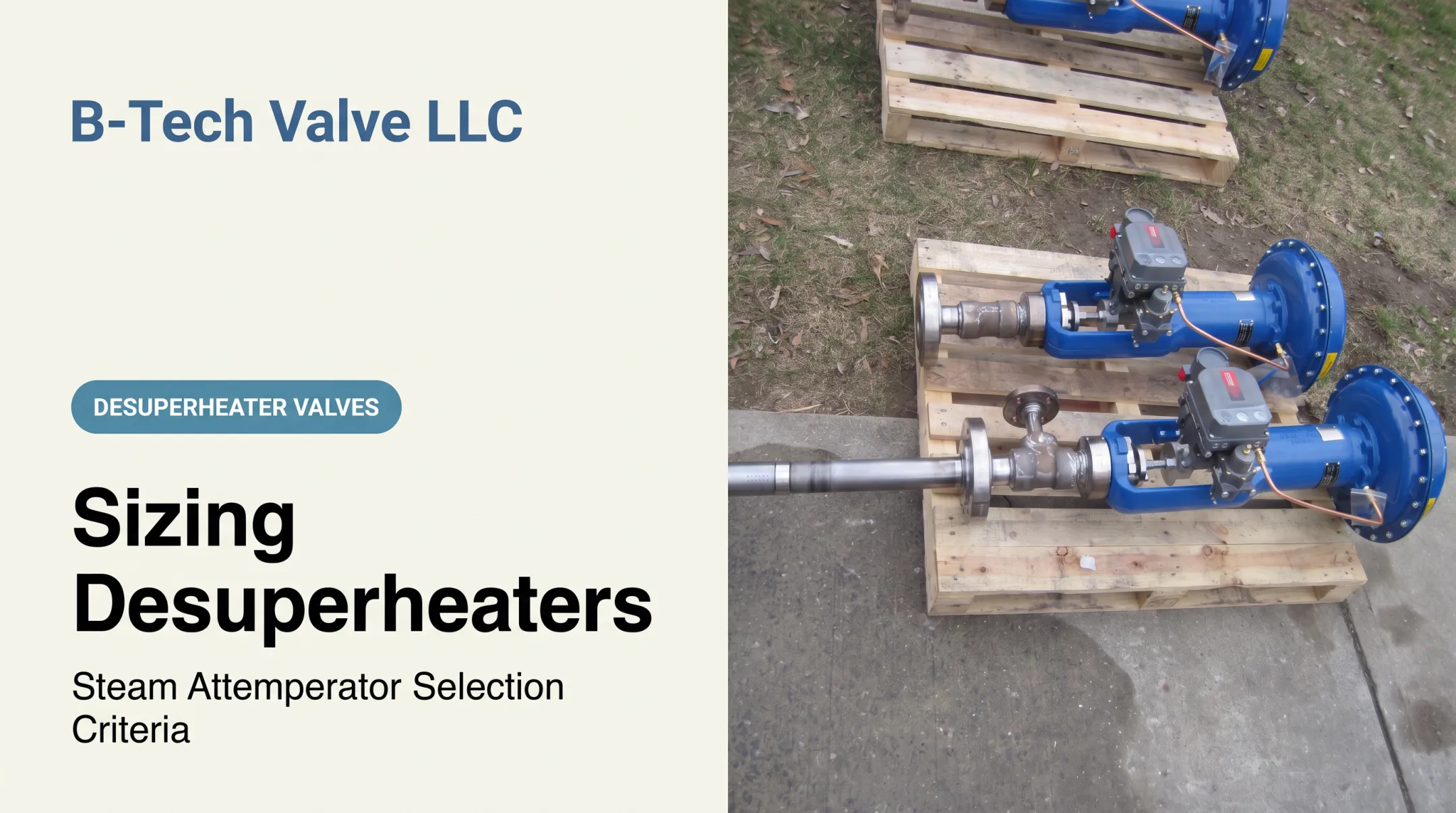
- LPD (Large Pipe Desuperheater): probe-type, variable-nozzle, fully actuated control valve and desuperheater assembly for steam pipes 6 inches and larger
- SPAD (Small Pipe Attemperator Desuperheater): spray-ring, fixed-nozzle unit for steam pipes 4 inches and smaller, paired with a separate temperature-control valve
Information to Have Ready Before Contacting Us
- Line size and schedule
- Steam pressure and temperature
- Mass flow range (minimum, normal, maximum)
- Required outlet temperature
- Allowable pressure drop
- Control-valve information, if applicable
- Materials and connection details
- Installation drawings, where available
If you're an engineer, plant operator, outage contractor, or valve distributor working through a desuperheater sizing or replacement decision, send your operating data to Sales@B-TechValves.com or call 609-321-2205. We'll review it against your application before recommending anything.
Frequently Asked Questions
How do I calculate pipe size for steam?
Start with steam mass flow, pressure, temperature or steam quality, allowable pressure drop, pipe length, and fittings. Convert mass flow to volumetric flow using specific volume, then size for actual internal diameter and verify both velocity and outlet pressure.
What is the rule of thumb for pipe sizing?
Rules of thumb (like 6,000–10,000 ft/min velocity ranges) work for preliminary screening only. They shouldn't replace a full calculator run, code review, pressure-drop analysis, or manufacturer-specific requirements.
What are the standard steam pipe sizes?
Standard nominal sizes and schedules vary by piping standard and supplier, referenced in standards like ASME B36.10M and B36.19M. The final nominal size comes after calculating required internal diameter and checking wall thickness against pressure rating.
What type of pipe is best for steam lines?
The right material depends on pressure, temperature, corrosion environment, applicable code, and joining method. Check qualified engineering documentation and material specifications rather than assuming one material fits every application.
Can you use PEX for a steam line?
Ordinary PEX shouldn't be assumed suitable for pressurized steam service. Its published temperature and pressure ratings typically fall below common steam conditions, so verify against the specific product listing, code, and your actual operating pressure and temperature.
How hot does a steam line get?
Line temperature depends on steam pressure, whether it's saturated or superheated, and insulation condition. Saturated steam at atmospheric pressure runs around 212°F, but pressure increases push that temperature much higher — check a steam table or manufacturer source for your specific conditions.