Introduction
Walk through any power plant or process facility, and you'll find pressure gauges, temperature readouts, and level indicators holding steady. Behind each one of those stable numbers, a valve is working continuously and mostly invisibly.
Globe control valves regulate flow, pressure, temperature, and liquid level throughout power generation and process plants. Many people picture a simple handwheel-operated device.
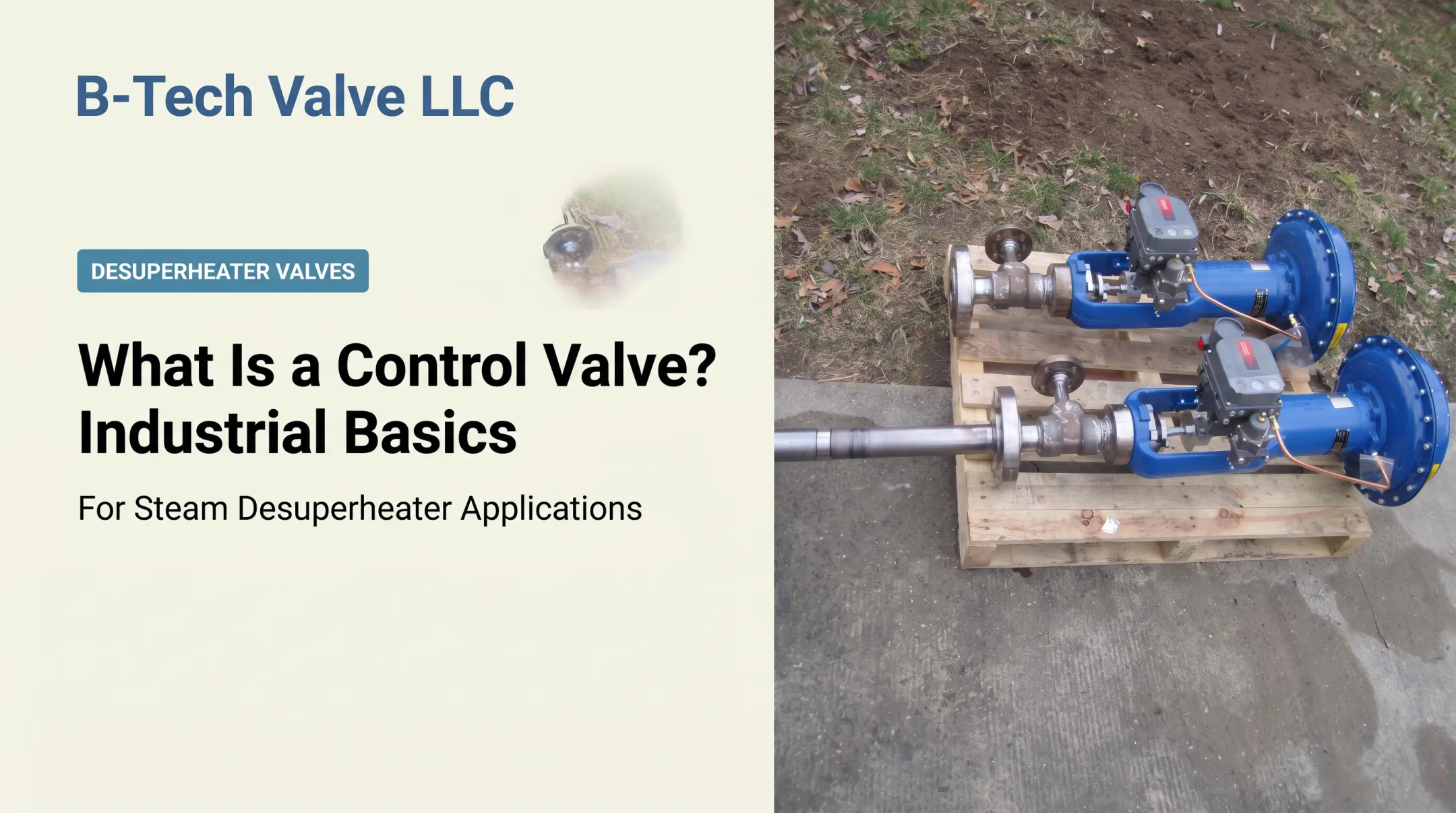
An automated globe control valve is different. It combines a body, trim, actuator, positioner, and control signal that work together to correct process conditions continuously.
This guide covers how that assembly functions: components, operating sequence, pressure-drop behavior, and its role inside a control loop. You'll also see common design patterns and where these valves show up in real plants.
Key Takeaways
- A globe control valve regulates flow by moving a plug toward or away from a fixed seat, changing the available flow passage
- An actuator converts a controller signal into stem movement, while a positioner helps the valve hold its commanded position
- The valve's tortuous internal flow path creates throttling authority but also pressure drop, turbulence, and cavitation risk
- T-pattern, angle-pattern, Y-pattern, and cage-guided trims each suit different pressure, space, and maintenance needs
- Globe valves excel where precise linear control and high pressure-drop handling matter more than compact size
What Is a Globe Control Valve?
A globe control valve is a linear-motion final control element that automatically varies fluid flow in response to signals from a process controller. That's the key distinction from a manually operated globe valve, which only changes position when a person turns a handwheel.
Plants need more than isolation. Pressure, temperature, level, and flow shift constantly as operating conditions change, and a valve that's simply open or shut can't keep up.
The globe control valve itself doesn't decide what the process should do, though. Sensors measure conditions, a controller calculates the correction, and the valve physically carries out that instruction by changing how much fluid passes through.
Core Components
Every automated globe control valve assembly shares the same basic building blocks:
- Body and bonnet – the pressure-containing structure; the bonnet houses the stem packing and often guides the stem
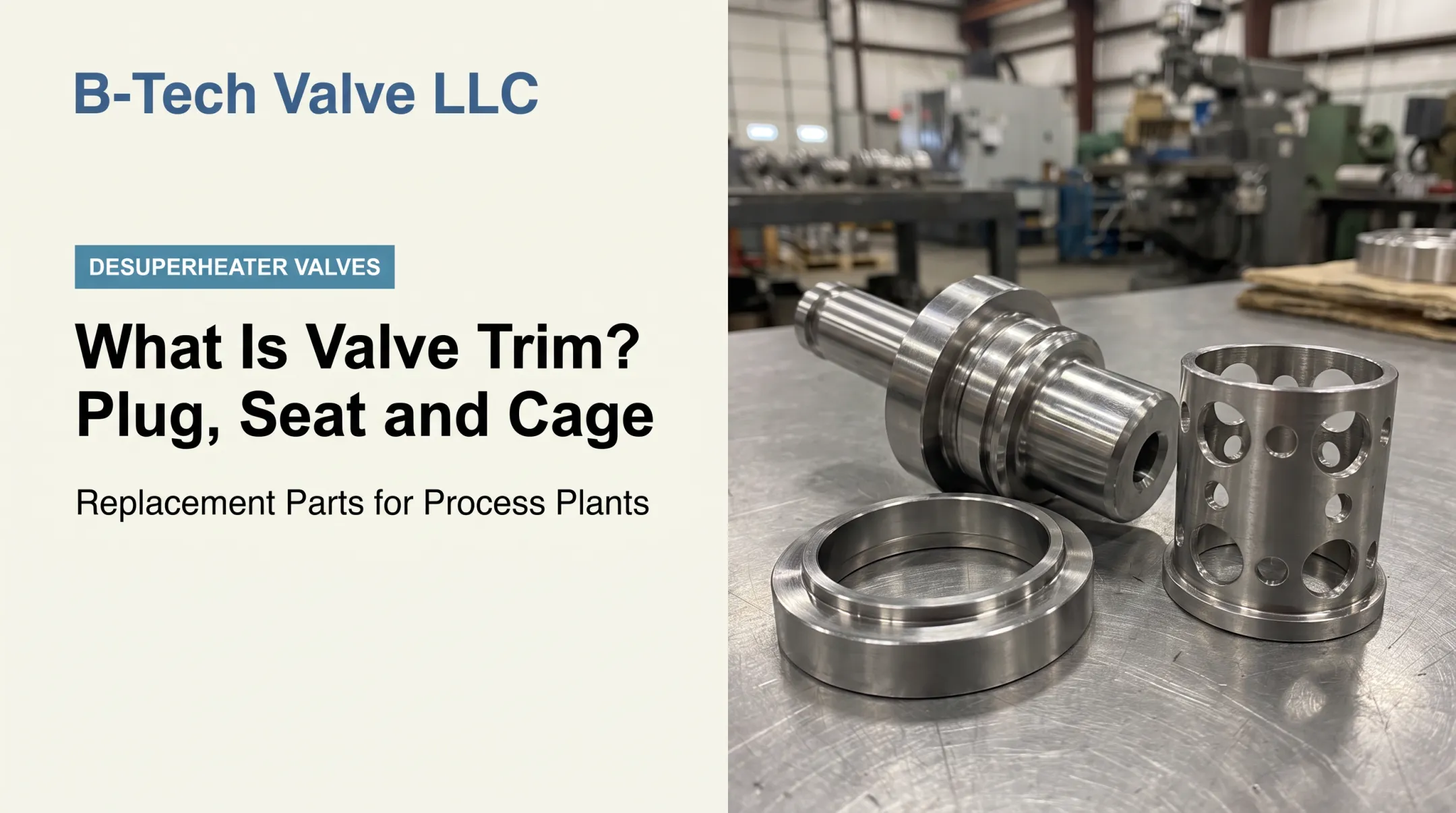
- Seat and plug – the primary throttling trim; the plug travels toward or away from a fixed seat ring to change the flow opening
- Stem – the linear-motion link connecting the actuator to the plug
- Actuator – supplies the pneumatic, electric, or hydraulic force that moves the stem
- Positioner – compares actual stem position against the command signal and corrects for friction, differential pressure, and hysteresis
- Packing – seals the stem where it passes through the bonnet, preventing process fluid from escaping
Globe Valves vs. Other Valve Types
Gate valves are generally chosen for isolation, not continuous throttling. Ball valves use rotary motion instead of linear motion and are often selected for fast shutoff or higher flow capacity.
A globe control valve also isn't the same thing as a pressure regulator, check valve, or desuperheater. Each of those performs a distinct protection or control function, even though they share a pipeline.

Body and trim design also varies by service:
| Type | Typical fit |
|---|---|
| T-pattern | Common across low- to high-pressure, small- to large-bore service |
| Angle-pattern | Turns flow 90 degrees, saves space, more associated with control than isolation |
| Y-pattern | Stem inclined roughly 45 degrees, lower restriction, suited to dirty or viscous fluids |
| Single-seat | Simple design, strong shutoff, requires actuator force to overcome unbalanced pressure |
| Cage-guided | Cage retains the seat ring and characterizes flow, supports balanced and anti-cavitation trims |
How Does a Globe Control Valve Work?
A globe control valve operates as one link in a feedback loop. A sensor measures the process variable, a controller compares that reading against the setpoint, and the valve changes position to close the gap between the two.
Initiation
The sequence begins when a controller sends a pneumatic, electric, or other compatible signal to the actuator based on a measured deviation in flow, pressure, temperature, or level. Legacy pneumatic signals commonly run 3–15 psig across the 0–100% travel range, though most modern systems now use 4–20 mA DC, converted to pneumatic pressure where needed.
Operation is usually continuous and automatic. A manual handwheel exists mainly for commissioning, testing, or non-automated service. For any of this to work correctly, the valve needs:
- A properly configured control signal
- Sufficient actuator power for the application
- A suitable fail-safe position
- Correct sizing for the installed service
Core Operation
The actuator moves the stem linearly, which pulls the attached plug away from or pushes it toward the seat. Lifting the plug opens the flow passage. Intermediate travel meters flow proportionally. Seating the plug restricts or stops flow entirely.
Inside the body, fluid has to change direction around the trim. That path creates more resistance than you'd see in a fully open ball or gate valve, and it is also what gives the globe valve its throttling precision.
Plug and seat geometry determine the valve's inherent flow characteristic. A linear characteristic produces flow changes proportional to travel; an equal-percentage characteristic produces equal percentage flow changes per increment of travel. The right choice affects how controllable the valve feels across its full operating range.
Flow coefficient (Cv) is the standard sizing input, but it's not the whole story. Pressure drop, fluid properties, noise, cavitation, flashing, and installed system behavior all need separate evaluation. The ISA's sizing standard provides the sizing equations engineers use for both compressible and incompressible flow under actual installed conditions.
Regulation / Control
The controller doesn't just command "open" or "closed." It repeatedly compares the actual process condition with the setpoint and nudges the actuator position accordingly. The positioner handles the fine detail (converting that command into accurate stem travel while correcting for friction, shifting differential pressure, and actuator hysteresis).

Pressure drop across the partially open trim is what gives the valve its control authority. Too little drop and the valve loses precision. Too much, and you risk wasted energy, instability, excess noise, or physical damage.
High pressure-drop services raise a few specific concerns:
- Cavitation – vapor bubbles form and collapse, producing gravel-like noise and cinder-like erosion
- Flashing – vapor bubbles persist downstream, causing smooth, polished-looking erosion
- Choking – flow stops increasing even as upstream pressure rises further
- Noise and vibration – turbulence and bubble collapse generate audible and sometimes damaging energy
Manufacturers address these with balanced trim, multi-stage trim, cage guidance, upgraded materials, and purpose-built anti-cavitation or noise-reducing designs. Noise prediction itself follows published methods : the IEC's noise standard covers aerodynamic noise from single-phase gases and vapors passing through control valves, including globe-style trims.
Output / Result
The immediate result of all this is simple: the valve changes how much fluid enters the downstream section of the system. That flow change is what actually stabilizes downstream pressure, holds steam temperature steady, adjusts feedwater flow, or regulates a chemical process stream.
How good that result is depends on valve sizing, rangeability, shutoff performance, actuator response, and calibration accuracy across the whole measurement-and-control loop. In the end, every installation balances control precision against pressure loss, wear, emissions, and maintenance demand.
Where Globe Control Valves Are Used
Globe control valves show up wherever a process needs repeated, modulated adjustment rather than occasional isolation — particularly in high-pressure, high-temperature, or high-pressure-drop service.
Common applications across U.S. power and process plants include:
- Boiler feedwater control
- Turbine steam and bypass systems
- Pressure-reducing stations
- Condensate systems
- Refinery utilities and chemical process lines
- Industrial boiler and cogeneration plants
Whether the valve ends up controlling flow, pressure, temperature, or level depends entirely on the surrounding instrumentation and process design.
Globe valves tend to win when the application demands strong throttling authority, predictable linear stem movement, high differential pressure, tight control accuracy, or replaceable specialized trim. Rotary alternatives often win when installation space is limited, flow capacity requirements are high, pressure drop is modest, or package weight and cost matter more than ultimate control precision.
One steam-system distinction is worth calling out directly. When a process needs to reduce the temperature of superheated steam, that job belongs to a desuperheater or attemperator, not a conventional globe control valve.
B-Tech Valve's LPD Large-Pipe Desuperheater handles 6-inch and larger steam lines using a probe-type, variable-nozzle design with an integrated actuated control valve. The SPAD Small-Pipe Attemperator Desuperheater covers 4-inch and smaller lines using a fixed-nozzle spray-ring design, paired with a separate temperature control valve. Both are purpose-built for steam conditioning rather than general throttling duty.

Conclusion
The working logic holds together simply: a controller requests a correction, the actuator moves the stem, the plug changes the seat opening, and the resulting flow change drives the process variable back toward its setpoint.
Understanding that chain makes for better valve selection decisions. Before specifying anything, evaluate:
- Fluid properties, pressure, and temperature
- Expected pressure drop and trim style
- Actuation type and control characteristic
- Maintenance access
- Real consequences of cavitation or noise in your specific service
If your application involves steam conditioning or related power and process equipment, talk through the specifics with B-Tech Valve's application engineering team rather than assuming a standard control valve will handle a steam-temperature problem it wasn't designed for.
Frequently Asked Questions
Can a globe valve be used as a control valve?
Yes. Globe valves are well suited to throttling and become automatic control valves once paired with an actuator, controller, and typically a positioner. A manually operated globe valve without these components is not a control valve.
Are globe control valves better than ball valves?
It depends on the application. Globe valves often deliver more precise throttling and better high pressure-drop handling, while ball valves can offer higher capacity, a more compact footprint, and faster rotary operation.
What is a globe control valve used for?
It automatically regulates flow, pressure, temperature, or liquid level in systems such as power generation, refining, chemical processing, and industrial steam plants, keeping a measured process variable close to its setpoint.
What is another name for a globe control valve?
It's sometimes called a linear-motion control valve, a throttling control valve, or, in the broader context of a control loop, a final control element.