Introduction
Walk through almost any US power plant, refinery, or chemical facility, and you'll find control valves that must land in the exact position a control system commands. That's rarely as simple as it sounds.
Stem friction, actuator limitations, shifting differential pressure, and the need for fast, repeatable movement all get in the way. A control valve positioner exists to close that gap between the signal sent and the position actually achieved.
Positioners are considered optional accessories for throttling control valves, not mandatory components for every automated valve, according to ISA's 2024 technical report on throttling control-valve service. Knowing when you actually need one matters.
This guide covers what a positioner is, how its feedback loop functions, how it differs from an actuator or controller, which types exist, and which applications genuinely call for one.
Key Takeaways
- A positioner compares commanded valve position with actual stem or shaft travel and adjusts actuator output to close the gap
- Positioners improve accuracy, response, and friction resistance but can't fix incorrect valve or actuator sizing
- Pneumatic, electro-pneumatic, and digital/smart positioners each have different signal, calibration, and diagnostic needs
- Demanding throttling, high differential pressure, split-range, and critical steam applications benefit most from positioners
What Is a Control Valve Positioner?
A control valve positioner is a feedback instrument mounted on or connected to a valve actuator. It receives a desired-position signal, measures the valve's actual travel, and adjusts actuator pressure or drive output until the valve reaches the commanded position.

An actuator receiving a signal alone doesn't always place the valve exactly where it's supposed to go. Friction, spring characteristics, linkage movement, packing resistance, and differential pressure all pull the actual position away from the intended one.
Four Components, One Loop
These four pieces are often lumped together in conversation:
- The process controller or DCS calculates the desired valve position from measured process conditions
- The positioner closes the local position loop and corrects the valve's actual travel
- The actuator supplies the force or motion that physically moves the valve
- The valve changes flow, pressure, temperature, or another process variable
A positioner is not the valve body, and it's not the actuator. It's also not necessarily the primary process controller, though some smart devices add control, communication, or diagnostic capability on top of their core positioning job.
The Three Main Configurations
| Positioner Type | Signal In | Output |
|---|---|---|
| Pneumatic | Pneumatic | Pneumatic |
| Electro-pneumatic | Electrical (often I/P, 4–20 mA) | Pneumatic |
| Digital/smart | 4–20 mA, HART, Fieldbus, or PROFIBUS | Pneumatic, with diagnostics and auto-calibration |
Pneumatic positioners stay in the air-signal domain and fit plants that already run pneumatic loops. Electro-pneumatic units add I/P conversion so a 4–20 mA signal can drive a pneumatic actuator. Digital or smart positioners add a microprocessor for auto-calibration, monitoring, and diagnostics over HART, Fieldbus, or PROFIBUS.
Whether you need one depends on the valve assembly and the process, not simply on whether the valve is automated. Basic on/off service and low-demand applications often skip the positioner. Precise modulating service usually doesn't.
How Does a Control Valve Positioner Work?
The sequence is straightforward once you see it laid out:
- A command signal enters the positioner
- The positioner senses actual valve position
- It calculates the error between command and feedback
- Actuator output changes in response
- The valve moves until the error shrinks enough to stop
Initiation
The positioner receives its desired-position signal from a pneumatic controller, DCS, PLC, or similar system. That signal typically arrives as a pneumatic input, a 4–20 mA electrical signal, or a digital communication protocol.
This isn't a one-time event at startup. During modulating control, the positioner works continuously. A setpoint change, a process disturbance, or a detected position error can all trigger a correction.
For any of this to function, a few things need to be in place:
- A compatible input signal from the control system
- Adequate instrument-air supply where pneumatic output is used
- Correct fail-action configuration
- A positioner mounted and linked correctly to the actuator
Core Operation
A position sensor or mechanical feedback linkage tracks linear stem travel or rotary shaft movement and reports it back to the positioner. If the valve isn't where the command says it should be, the positioner adjusts its output to the actuator. Once the valve reaches target, output stabilizes.
Pneumatic units typically rely on a relay, spool, nozzle, diaphragm, or cam arrangement to achieve this force balance. The actuator then converts that corrected air pressure (or electrical drive signal, for electric actuators) into linear or rotary movement of the plug, ball, disc, or vane.

Regulation and Control
Feedback is what makes the positioner effective. It helps counter:
- Stem packing friction and stiction
- Actuator spring variation and linkage effects
- Changing forces from differential pressure across the valve
Better travel consistency reduces deadband, improves repeatability, and makes the valve's behavior more predictable to the main controller.
A positioner can also provide high-capacity air delivery or amplification for faster stroking. What it cannot do is overcome an undersized actuator, inadequate supply pressure, blocked air lines, or a valve that was never correctly selected for the application in the first place.
Several control functions matter here too:
- Split-ranging: a controller signal can be divided across two valves. A common example splits 4–12 mA to one valve and 12–20 mA to a second, according to SAMSON's positioner manual
- Signal characterization: linear, equal-percentage, or custom response curves
- Direct or reverse action: matching the positioner's response direction to the process need
- Fail-safe configuration: fail-freeze holds last position, while fail-safe drives the valve open or closed on signal or air loss, per ABB's positioner guide
Output and Result
The end result is valve travel that tracks the requested signal despite friction, pressure swings, and other mechanical disturbances. Downstream, that means steadier steam temperature, tighter pressure or flow control, and better equipment protection.
One caution worth repeating: faster isn't automatically better. A positioner's tuning and speed need to match the process loop. An overly aggressive or poorly configured positioner can introduce oscillation instead of fixing it.
The signal path, in sequence, looks like this: controller signal → positioner → actuator → valve movement → feedback → correction.
Where Are Control Valve Positioners Used?
In a typical operational flow, a process sensor reports a condition, the controller calculates a command, the positioner verifies valve travel, the actuator moves the valve, and the resulting flow or pressure change feeds back into the process.
Applications Where a Positioner Is Commonly Needed
- Tight temperature, pressure, flow, or level control where small positioning errors threaten safety, quality, or equipment protection
- High or variable differential pressure, high packing friction, long stroke, large actuator volume, wide throttling range, or service involving suspended solids
- Split-range systems, nonstandard signal or spring ranges, springless double-acting actuators, or applications requiring remote diagnostics or partial-stroke testing
- Steam and process applications where accurate modulation supports heat transfer, pressure reduction, or steam conditioning
Where It May Be Unnecessary
Basic on/off service, simple low-friction valves, low differential pressure applications, and slow process loops are all situations where a positioner may add unneeded dynamics rather than solve a real problem. Evaluate case by case rather than assuming every automated valve benefits.
Selection and Installation Checklist
Before specifying a positioner, confirm:
- Valve and actuator compatibility, including linear versus rotary travel
- Input signal type matches what your control system provides
- Air pressure and capacity are sufficient for the actuator volume
- Fail position is correctly configured for the application
- Environmental and hazardous-area ratings are satisfied
- Feedback linkage, calibration method, and communication protocol are confirmed
- Clean, dry instrument air is available and reliable
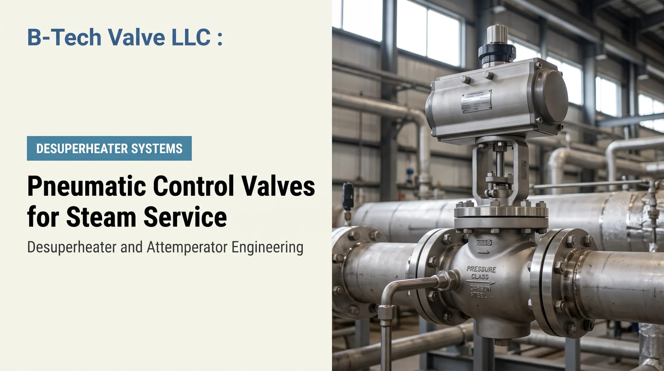
Steam-conditioning systems are a good example of where accurate actuation and feedback pay off. B-Tech Valve's LPD Large Pipe Desuperheater combines a variable-nozzle, actuated control valve and desuperheater in one assembly, built for steam pipes 6 inches and larger, with pressure ratings from ASME B16.34 Class 150 through 2700 and temperatures to 1200°F. Repeatable water and steam control in these systems depends on correctly actuated valve movement.

Positioner compatibility and inclusion need to be confirmed for your specific assembly. If you're sizing a desuperheater for a steam-conditioning project, talk with B-Tech Valve's application engineering team before finalizing the specification.
Conclusion
A control valve positioner closes the local loop between a commanded signal and the valve's actual travel, then adjusts actuator output until the two match. That's the whole job, done continuously, under real process conditions.
Making good decisions means asking the right questions upfront:
- Does this application actually need feedback correction?
- Does the positioner match the valve and actuator?
- Are air and electrical requirements verified?
- Is pneumatic, electro-pneumatic, or smart technology the right fit?
Answer those honestly, and the positioner choice tends to fall into place.
Frequently Asked Questions
Do all control valves have positioners?
No. Simple on/off or low-demand applications often run without one. Precise modulating, high-friction, high-differential-pressure, split-range, or critical process applications frequently benefit from or require one.
What is the difference between an actuator and a positioner?
The actuator supplies the force and motion that moves the valve. The positioner compares commanded and actual travel, then adjusts actuator output to correct any difference.
What is the difference between a valve controller and a positioner?
The process controller responds to the measured process variable and generates a valve command. The positioner works locally, verifying and correcting the valve's physical position to match that command.
How do control valve positioners work?
A positioner receives an input signal, measures actual valve travel through a feedback sensor, calculates the error, and adjusts actuator output accordingly. The valve keeps moving until it reaches the requested position.
What are the different types of valve positioners?
Pneumatic positioners use pneumatic signals throughout. Electro-pneumatic units accept an electrical input and output pneumatic pressure. Digital or smart positioners add microprocessor-based diagnostics, auto-calibration, and digital communication.
What is an electro-pneumatic positioner?
It accepts an electrical control signal, commonly 4–20 mA, and converts that command into pneumatic output for a pneumatic actuator. Check product documentation closely, since some electro-pneumatic devices also include digital intelligence.