In a typical plumbing system, a generic valve works fine. In a power or process plant, it rarely does. High temperatures, steep pressure differentials, corrosive or hazardous media, round-the-clock operation, and the cost of unplanned downtime all push specification decisions far beyond line size and connection type.
This guide covers control-valve fundamentals, the major valve and actuator types used in power and process service, where these valves show up across plant systems, how to select one correctly, and the specific role desuperheaters play in conditioning steam for downstream equipment.
Key Takeaways
- Valve body, actuator, trim, control signal, fail position, and process conditions work as one system, not separate decisions
- Steam and process service needs application-specific sizing; line size alone won't get you there
- Correct selection supports stable control, equipment protection, and easier long-term maintenance
- Desuperheaters require their own engineering review beyond standard control-valve selection
What Is an Industrial Control Valve?
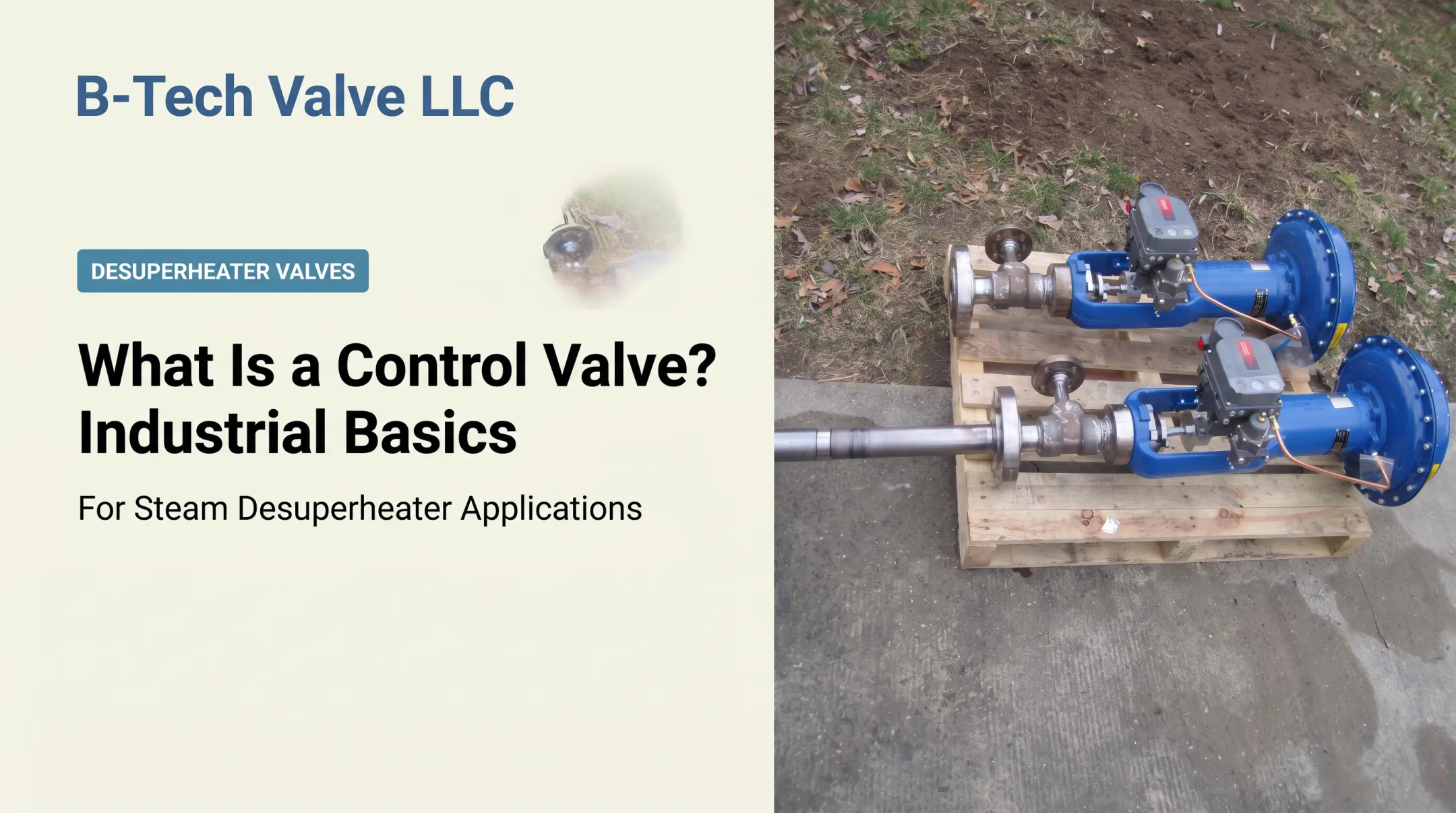
An industrial control valve is a power-operated device that modulates or restricts fluid flow in response to a signal from a controller: a PLC, DCS, or dedicated control system. It's the muscle at the end of a control loop.
The loop itself is straightforward. A sensor measures a process variable such as pressure or temperature, a controller compares that reading to a setpoint, and the actuator repositions the valve to correct the difference. ISA describes this arrangement as measuring and control elements working together, with valves serving as the final control elements.

Not every automated valve belongs in this category. A valve can be automated, motor-operated or air-operated, without being designed for continuous throttling. Isolation valves, check valves, and pressure-relief devices all move automatically or passively, but they're built for shutoff, backflow prevention, or overpressure protection, not for holding a process variable steady. VMA distinguishes a control valve's proportioning function from a check valve's backflow prevention and a relief valve's overpressure protection: three different jobs, not interchangeable labels.
Valve Assembly and Control Elements
A control valve is an assembly of parts working together, not a single piece of hardware:
- Body: the pressure boundary and flow passage
- Closure element and seat: the parts that actually restrict flow
- Stem or shaft: connects the closure element to the actuator
- Actuator: supplies the force or motion to position the closure element
- Positioner and accessories: fine-tune actuator position against the control signal
Actuation comes in three flavors. Pneumatic actuators use plant air and are common where fast response and simple fail-safe action matter. Electric actuators suit locations without instrument air, and some models include backup power and field-settable fail direction. Hydraulic actuators deliver high force in a compact package, often for large or high-torque valves.
Each type raises its own questions. What utilities are already available? How fast does the valve need to respond? Is the area classified as hazardous?
Fail position is a safety decision, not an afterthought. Fail-open, fail-closed, and fail-in-place all protect different outcomes. The right choice depends on what happens downstream if you lose air, power, or signal, not on what's convenient to specify.
Common Types of Industrial Control Valves
Valve types split into two families based on how the closure element moves. Linear-motion valves, such as globe and angle valves, raise and lower a plug or disc along a straight path. Rotary-motion valves, including butterfly, ball, and eccentric plug valves, turn a quarter-turn to open or close.
Globe and angle valves are frequently chosen for precise throttling, high pressure drops, steam service, and severe-service applications. Final suitability still depends on sizing, trim, and actual operating conditions; body style alone doesn't guarantee performance.
Quarter-turn designs cover different ground:
- Butterfly valves: compact, lightweight, good for large-diameter lines, but offer the narrowest control range among common styles
- Ball valves, including V-notch: V-notch designs provide wide rangeability and work well in erosive, viscous, or solids-bearing service
- Eccentric plug valves: cammed seat motion reduces friction and wear, useful in erosive or coking service
Actuator choice shapes how any of these valves perform in the field:
| Actuator type | Typical strength | Watch for |
|---|---|---|
| Pneumatic | Simple fail-safe action via spring return | Requires reliable instrument air |
| Electric | No air supply needed; some units offer backup power | Explosion-proof rating needed in classified areas |
| Hydraulic | High force in a compact footprint | More complex fluid power system to maintain |
Trim, flow characteristic, rangeability, and resistance to cavitation, erosion, and noise often matter more than body style itself. Two globe valves from two manufacturers can perform very differently once trim design, seat leakage class, and flow direction are factored in.
Continuous Modulating, On/Off, and Pressure-Control Service
Not every automated valve is meant to modulate continuously. A valve intended for isolation, emergency shutdown, or diversion typically sits fully open or fully closed. A modulating control valve is designed to throttle anywhere across its stroke, often for extended periods.
Three categories get confused often:
- Pressure-reducing or pressure-regulating valves: maintain a set downstream pressure during normal operation
- Pressure-relief or safety valves: open only to discharge excess pressure, protecting equipment from an abnormal condition
- Control valves: continuously modulate flow, pressure, temperature, or level per a control signal
ASME's PTC 25 covers testing for pressure-relief devices specifically, kept separate from normal pressure-control equipment. That's a good reminder these aren't interchangeable terms. Always verify terminology against your plant's specification and applicable code before ordering or replacing a valve.
Where Control Valves Are Used in Power and Process Plants
Power plants lean on control valves throughout the steam cycle:
- Steam temperature control downstream of superheaters and reheaters
- Pressure reduction between high-pressure and low-pressure systems
- Feedwater and auxiliary utility flow control
- Turbine bypass and protection during startup, shutdown, or load swings
Process plants, including refineries, chemical facilities, pulp and paper mills, and rubber manufacturing, use the same fundamentals to control steam, gas, liquids, pressure, temperature, and heat-transfer conditions across dozens of loops.
Industrial boilers, cogeneration plants, waste-to-energy facilities, campus steam systems, and district-heating networks share one recurring need: conditioning steam downstream of a pressure-reducing station so it matches what downstream equipment can handle.
A pressure-reducing valve drops pressure, but it doesn't remove the superheat that comes with it. That's a separate job.
Done right, these valves protect:
- Piping and steam traps from excess velocity or temperature
- Rotating seals from thermal and pressure stress
- Heat exchangers and turbines from unstable flow conditions
A 2017 engineering study archived in OSTI's research database examined a gas-turbine HRSG plant where simulation and operating data both pointed to possible saturation in a final high-pressure superheater during load changes. An attemperator was working to control steam temperature.
The proposed fix coordinated attemperator setpoints with strategic control of the steam-turbine inlet pressure valve. Temperature control and pressure control in a steam system aren't independent problems. They interact, and specifying one without considering the other invites instability.

Operating Conditions That Make These Applications Challenging
Several operating realities shorten valve and trim life faster than anything else:
- Flashing: pressure drops below the fluid's vapor pressure and stays there downstream, causing persistent vapor bubbles and trim erosion near the seat
- Cavitation: pressure recovers above vapor pressure, bubbles collapse, and the result is gravel-like noise plus pitted, cinder-like damage
- Water hammer: high-velocity condensate slugs collide with fittings or equipment, risking sudden mechanical damage
- Thermal cycling: repeated heating and cooling drives thermal fatigue and thermal shock, particularly in components sitting in a hot zone
- Corrosive media and particulate contamination: accelerate wear on seats, trim, and packing over time
Continuous or critical processes can't treat valve failure as a surprise. Plan for maintainability upfront:
- Bypass piping where shutdown isn't an option
- Spare parts on hand
- Inspection access built into the layout
- A documented response plan before something fails, not after
No single valve style wins every power or process application. The right choice always comes down to the specific combination of pressure, temperature, media, and duty cycle in front of you.
Steam Conditioning and Desuperheater Valves
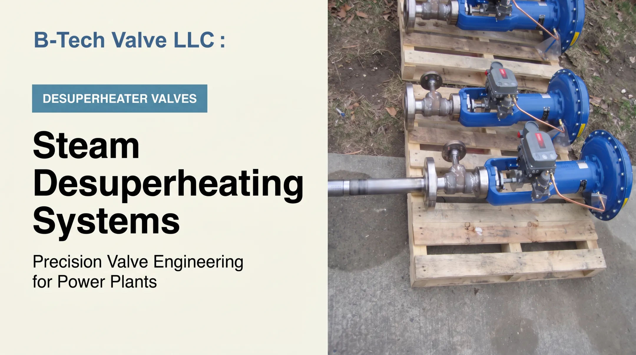
Desuperheating, also called attemperation, is the controlled injection of water into superheated steam to bring its temperature down to whatever downstream equipment, heat exchanger, or process requires.
It sounds simple. It isn't. A desuperheater has to manage water injection, droplet atomization, the distance steam needs to fully absorb that water, steam velocity, downstream temperature feedback, and the real risk of wet steam or thermal shock if any of that goes wrong.
Power Magazine's analysis of steam attemperation notes that components sitting in the hot zone face genuine thermal-fatigue and thermal-shock risk. This isn't only a temperature-control problem; it's a reliability problem.
That's a different design challenge than sizing a general-purpose control valve for a liquid or gas service, and it's where B-Tech Valve focuses its entire product line.
Two product paths, split by pipe size:
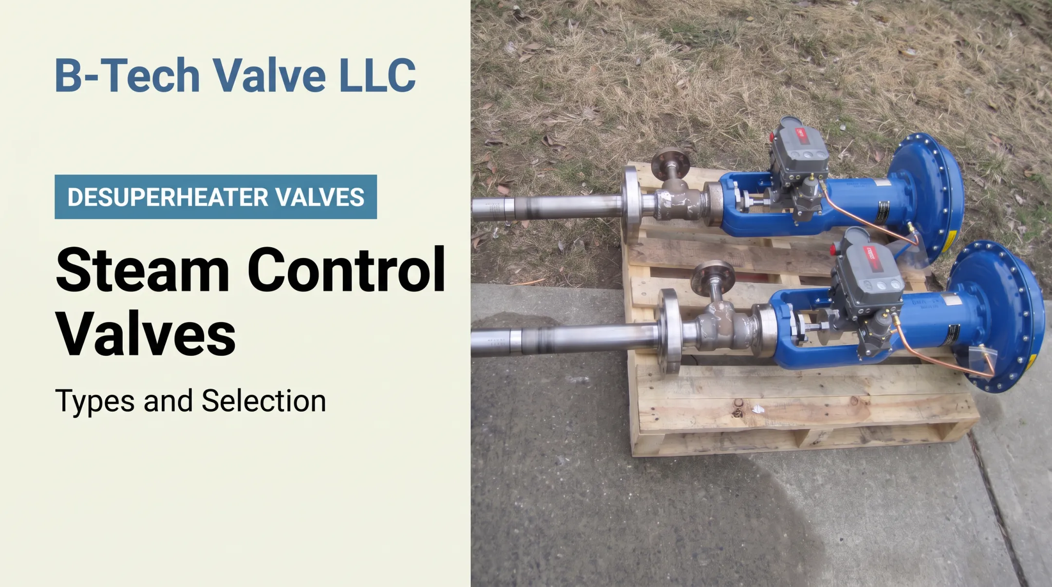
- LPD (Large Pipe Desuperheater): a probe-type, variable-nozzle control valve and desuperheater combined into one actuated assembly, built for steam piping 6 inches and larger
- SPAD (Small Pipe Attemperator Desuperheater): a spray-ring, fixed-nozzle unit that clamps between steam pipe flanges, fed by a separate temperature-control valve, for steam piping 4 inches and smaller
Both are offered across ASME B16.34 pressure classes 150 through 2700, for temperatures up to 1,200°F (650°C). Components come from U.S. machine and fabrication shops, with final assembly and testing done in-house.

Founder Charles Bauer built that model after a previous employer moved manufacturing offshore. Products are stocked, which matters during an outage when waiting on an order isn't an option.
Before evaluating any desuperheater, have this data ready:
- Steam inlet and outlet pressure
- Inlet and target outlet temperature
- Flow range and turndown
- Pipe size and available straight-run length
- Water pressure and quality
- Control signal and required fail position
- Materials of construction
Submit this upfront and an application review moves faster. It's the same information B-Tech Valve's own sizing data sheet asks for.
How to Select an Industrial Control Valve
Start with the process objective, not the catalog. Decide whether the valve needs to control flow, pressure, temperature, level, steam quality, or some combination, then define normal, minimum, maximum, startup, upset, and shutdown conditions. A valve sized only for normal operation often struggles the moment conditions shift.
Sizing requires real data, not estimates:
- Fluid or steam properties
- Flow rate (minimum, normal, maximum)
- Inlet and outlet pressure, and the resulting pressure drop
- Temperature and density
- Viscosity, for liquid service
- Line size
- Allowable noise level
- Required flow coefficient (Cv or Kv)
Recognized sizing standards such as IEC 60534 and the corresponding ISA methods exist for exactly this reason. Use them, or have your supplier's application engineer use them, rather than relying on rule-of-thumb formulas.
Once the duty is sized, material and trim selection follows from the operating environment:
- Corrosion and erosion resistance for the specific media
- Flashing and cavitation resistance where pressure drops are severe
- Solids handling where particulate is present
- Pressure class and leakage-rate requirements
- Compatibility with temperature extremes
Actuator and accessory decisions come next:
- Pneumatic, electric, or hydraulic power, based on what utilities already exist
- Positioner requirements and control signal type
- Required response time
- Environmental protection and hazardous-area classification
- Fail-safe action: open, closed, or in-place
Finally, don't overlook installation details. Flow direction, orientation, downstream piping, sensing location, and straight-run requirements all affect control stability. A valve engineered correctly on paper can still hunt, oscillate, or wear prematurely if it's installed wrong.

Specification and Replacement Checklist
Replacing an existing valve? Gather this before calling anyone:
- Valve tag and service description
- Line size and connection details
- Pressure class and materials
- Operating envelope and flow data
- Actuator data (power type, force or torque, fail action)
- Existing drawings and photographs
- Maintenance history
- Delivery deadline
A drop-in replacement isn't automatically interchangeable. Face-to-face dimensions, actuator force or torque, control signal, trim, connection type, and fail action all need verification. Matching the line size isn't enough on its own.
Bring in an application engineer when the service involves high-temperature steam, a severe pressure drop, unusual turndown, difficult water quality, or a valve that keeps failing for reasons nobody has pinned down.
Repeated failure almost always means the original specification missed something, not that the valve was simply unlucky.
If your plant is evaluating a desuperheater replacement or a new application, B-Tech Valve's team reviews operating data directly. Send steam and water conditions to Sales@B-TechValves.com or call 609-321-2205 to start an application discussion.
Conclusion: Matching the Valve to the Process
Industrial control-valve performance never comes down to one component. Body design, trim, actuator, control system, installation, and actual process conditions all interact, and getting one wrong means the rest can't compensate.
For steam conditioning specifically, that interaction gets tighter. Pressure, temperature, water quality, and pipe geometry all have to line up before a desuperheater does its job correctly.
Careful application data, properly engineered steam conditioning, maintainable components, and dependable replacement support won't guarantee a specific dollar figure in savings. They do give plants a real shot at protecting equipment and keeping operations stable. Start with the data; the right valve follows from there.
Frequently Asked Questions
What are the different types of process control valves?
Linear-motion valves (globe, angle) move a plug or disc in a straight line. Rotary-motion valves (butterfly, ball, eccentric plug) use a quarter turn. Actuator choice and service conditions decide which design fits best.
What is a process control valve?
It's a valve that modulates process conditions such as flow, pressure, temperature, or level in direct response to a signal from a control system. The complete assembly includes the body, actuator, and accessories needed for normal operation.
What is an automatic control valve?
An automatic control valve uses an actuator and a control signal to move without continuous manual operation. That's different from continuous modulation; some automatic valves are built only for automatic on/off service, not throttling.
What are industrial valves used for?
Industrial valves handle isolation, throttling, pressure control, flow direction, safety protection, steam conditioning, and equipment protection across power and process plants. The specific job determines which valve type and trim belong in that service.
What are the two types of PRV?
PRV usually means a pressure-reducing valve that holds downstream pressure, or a pressure-relief valve that opens only on overpressure. Confirm the intended meaning against your plant specification.
What is a PRD valve?
PRD can mean either a pressure-relief device or a pressure-reducing device, depending on the document you're reading. Always confirm the definition against the applicable plant standard, datasheet, or P&ID before acting on it.