Get it wrong and the consequences are real. Steam that runs too hot can damage piping, steam traps, and rotating seals. Poorly controlled desuperheating can quench piping locally, send water carryover toward a turbine, or create hot and cold zones that throw off temperature readings entirely, according to Emerson's steam research.
This article follows the actual signal path of a steam temperature control loop—measurement, comparison, correction, and feedback—rather than treating control theory as an abstract exercise.
Key Takeaways
- Control loops measure steam temperature, compare it to a set point, and drive a final element to close the gap.
- Core hardware: temperature sensor, controller, actuated valve or desuperheater, spray-water supply, and the steam process.
- Closed-loop feedback matters most when steam flow, pressure, or load conditions change often.
- Sensor placement, mixing distance, and valve sizing shape performance as much as the controller does.
- Desuperheaters change steam temperature; the control loop decides when and how much correction is needed.
What Is a Steam Temperature Control Loop?
A steam temperature control loop is a closed-loop arrangement that holds steam temperature near a chosen set point, even as steam flow, pressure, load, or heat demand shift underneath it.
A few terms do most of the work here:
- Process variable (PV) – the measured steam temperature, typically read downstream of the spray zone
- Set point (SP) – the target temperature the process should hold
- Error – the gap between measured and desired temperature
- Controller output – the signal sent to correct that gap
- Manipulated variable – usually spray-water flow
- Final control element – the valve or desuperheater that actually changes flow
It helps to separate two things people often blur together: the control loop and the desuperheater. The loop measures conditions and decides a correction is needed. The desuperheater is the hardware that injects and mixes water to actually lower the steam temperature. One decides; the other acts.

Closed-Loop vs. Open-Loop Operation
Open-loop control (a fixed or timed spray-water command) never checks whether the downstream temperature actually landed where it should. Closed-loop control does. It measures the result and adjusts the next command based on what it finds.
Two broad control approaches show up in practice:
- On/off control – simple, used where tight temperature bands aren't critical
- Modulating PID control – continuous correction, used where tighter temperature management matters
Most power and process-steam applications lean on modulating control, because load swings and pressure changes happen too often for on/off logic to keep up.
How Does a Steam Temperature Control Loop Work?
The loop runs as a continuous cycle: measure the steam condition, compare it to the set point, calculate a correction, move the final control element, then measure again. That cycle never really stops. It just keeps repeating as conditions shift.
Measurement: Sensing Downstream Steam Temperature
A temperature sensor, often a thermocouple or resistance temperature detector, reads steam temperature after the injected water has had room and time to evaporate and mix. Placement is not a minor detail.
- Too close to the injection point: the sensor can catch incomplete mixing or stray water droplets, skewing the reading
- Too far downstream: the loop picks up excess dead time, making the controller react to conditions that already changed
A transmitter or signal-conditioning device converts that sensor reading into a signal the controller can use, display, trend, and alarm on. When selecting and locating the measurement point, engineers typically weigh:
- Steam velocity and pipe geometry
- Expected temperature range and pressure
- Load changes and the mixing distance the desuperheater design requires
Comparison and Controller Decision
The controller stacks the measured value against the set point and works out the error. Temperature running high means the controller calls for more cooling. Temperature running low means it backs off.
A modulating PID controller typically blends three behaviors:
- Proportional action responds to the size of the current error
- Integral action accumulates error over time to eliminate lingering offset
- Derivative action adds a degree of stability against sudden swings
There's no universal tuning setting that works across every steam system. Process dead time, line size, and load variability all factor in, according to ISA's PID guide. Get the controller action or tuning wrong and the loop hunts, overshoots, or lags behind actual conditions.
Some applications add cascade, feed-forward, ratio, or override strategies on top of basic PID. Those options help when steam flow or spray-water pressure needs extra coordination, though they are refinements rather than requirements for every loop.
Final Control Element: Actuated Desuperheater or Control Valve
The controller's output signal drives an actuator or positioner, which opens or closes a spray-water valve or changes the effective flow area on an integrated desuperheater. More spray water means more evaporative cooling and a lower steam temperature. Less water lets the temperature rise.
Here's the part that's easy to overlook: the controller commands a valve position, but the actual temperature result depends on more than that command. Water pressure, available flow, nozzle performance, steam velocity, and mixing quality all shape the outcome.
This is where equipment design becomes part of the control strategy, not separate from it. Valve sizing, rangeability, pressure drop, materials, and actuator response all need to match the steam system and the control objective, not just the line size.
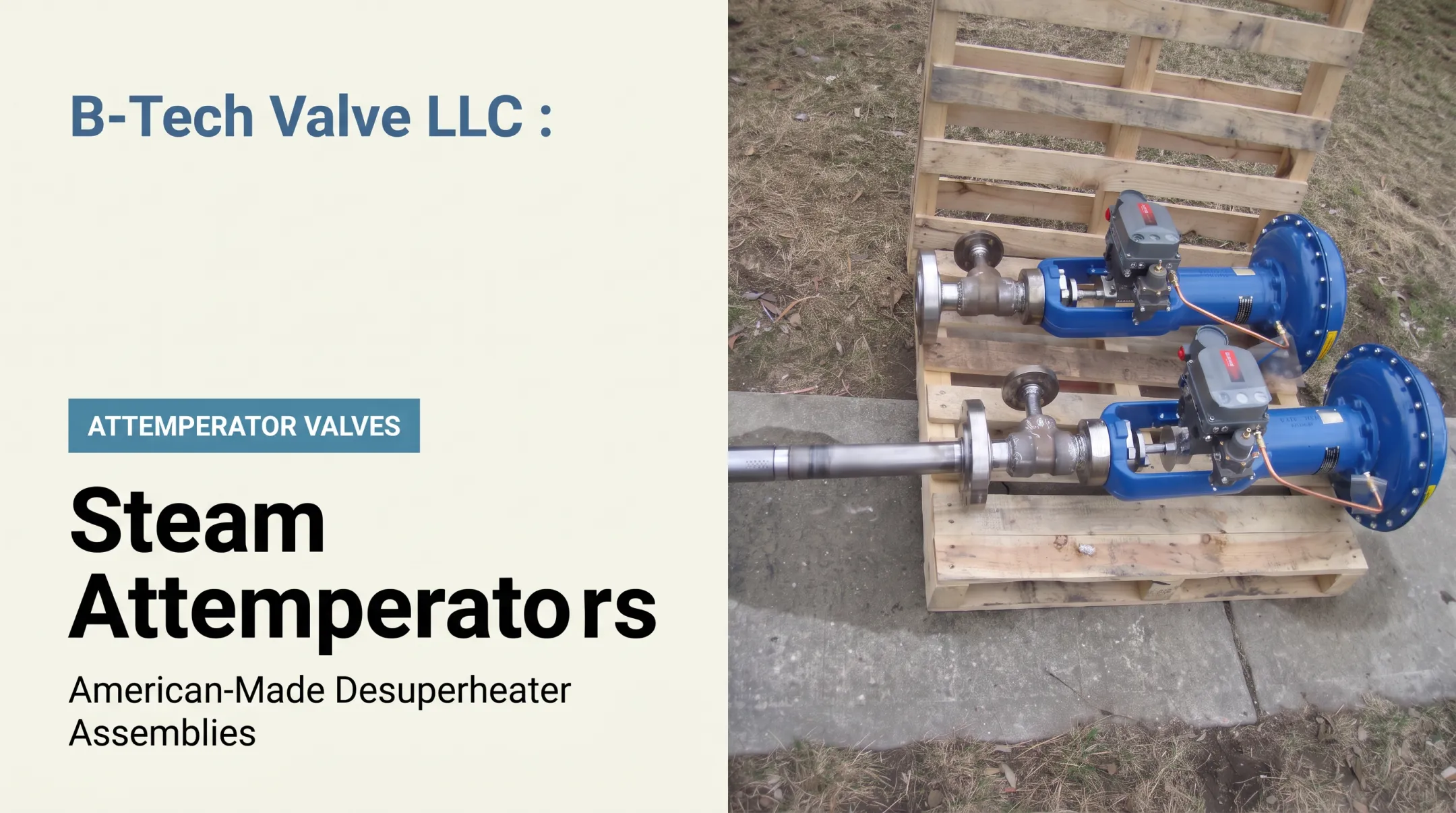
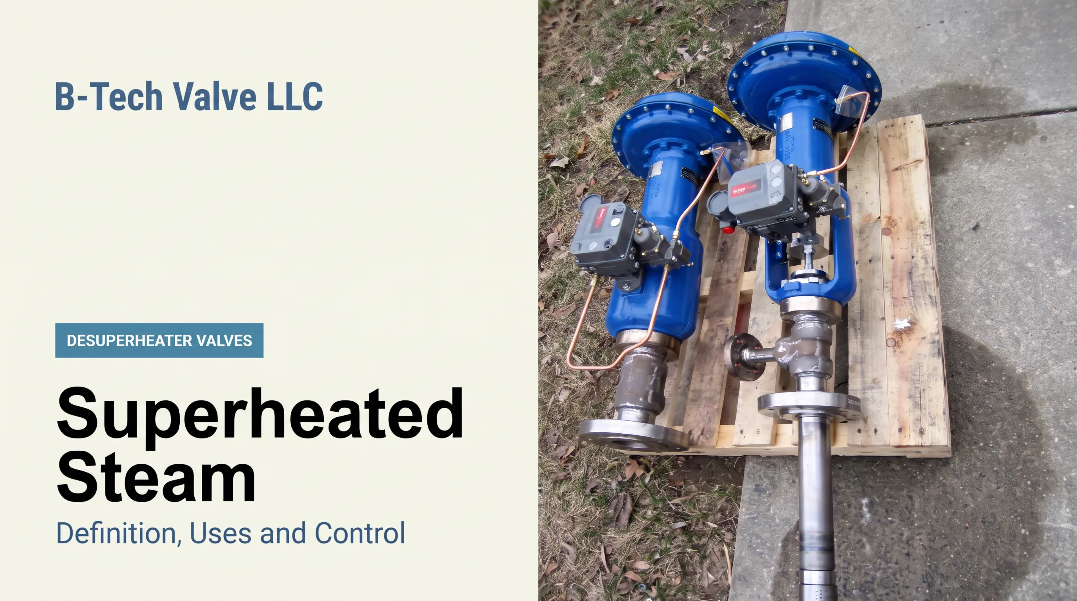
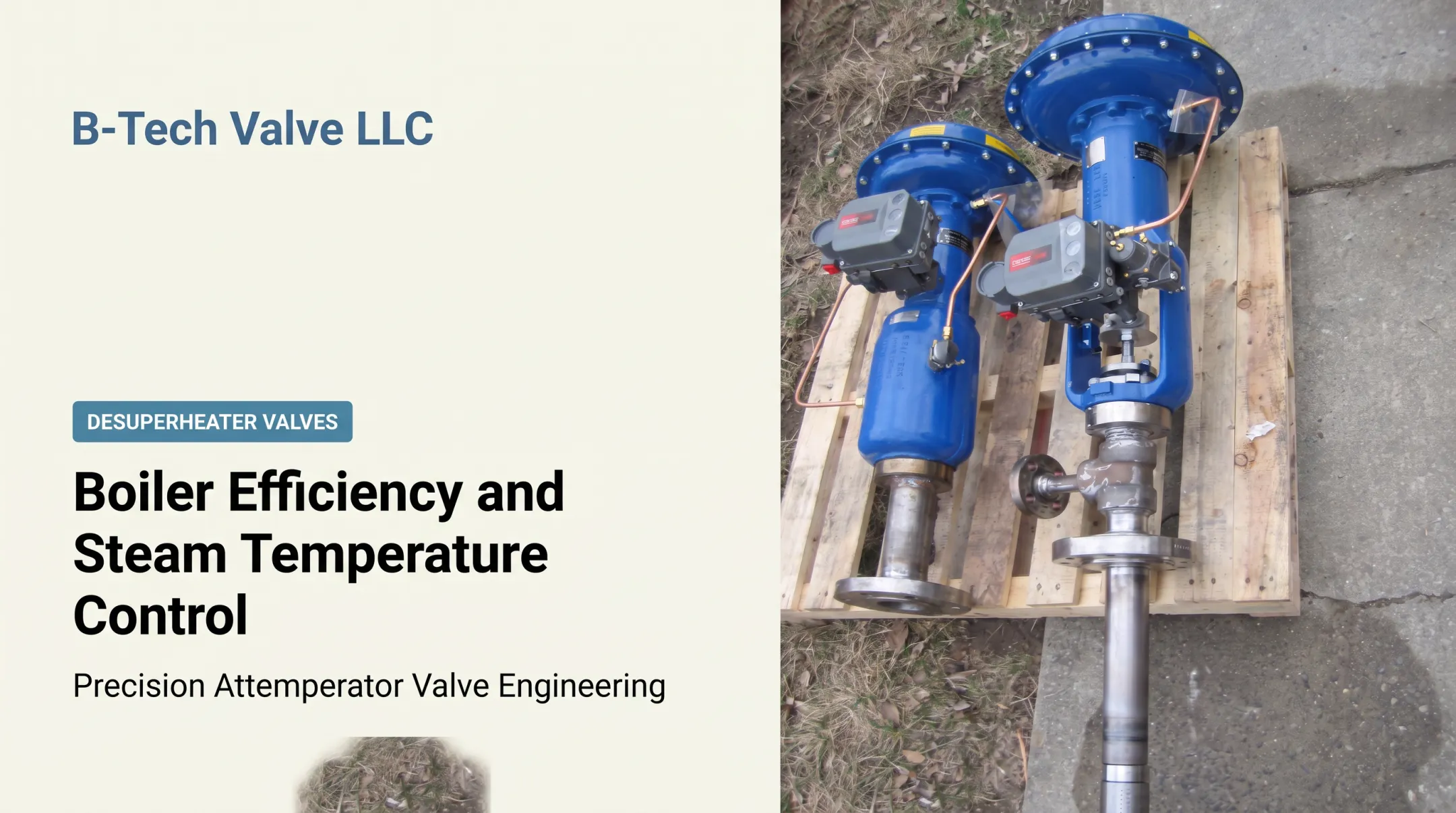
B-Tech Valve builds this into its product line directly. The LPD combines a probe-type, variable-nozzle, fully actuated control valve and desuperheater in one assembly for steam pipes 6 inches and larger. The SPAD is a fixed-nozzle spray-ring design for 4-inch and smaller lines, fed by a separate temperature control valve.
Feedback, Protection, and Output
Once the final control element moves, the corrected downstream temperature becomes the next measured value. The controller keeps adjusting as conditions change—that's the feedback cycle closing.
Protective functions typically layered into a well-designed loop include:
- High-temperature alarms
- Low-temperature or wet-steam protection
- Spray-water pressure permissives
- Minimum steam-flow requirements
- Isolation logic and manual fallback
A simple way to picture the whole arrangement: set point → controller → actuator/desuperheater → steam process → temperature sensor/transmitter → back to the controller, with steam load and pressure changes entering as disturbances along the way.

Where Steam Temperature Control Loops Are Used
Steam temperature control loops show up anywhere superheated steam needs to meet a downstream temperature requirement. Common settings include:
- Boiler and HRSG systems
- Turbine-related steam piping
- Refinery and chemical processes
- Pulp and paper operations
- Cogeneration plants
- Waste-to-energy facilities
- District and campus steam systems
Pulp and paper is a good example of how steam-dependent these industries really are. Steam accounts for 84% to 92% of total energy use in that sector, according to DOE's steam assessment. When steam carries that much of the plant's energy load, temperature control stops being optional.
Feedback control earns its keep where conditions don't hold still:
- Variable steam demand across shifts or seasons
- Changing boiler load
- Pressure-reducing stations feeding sensitive downstream equipment
- High-temperature superheated steam with tight tolerance requirements
- Processes that need repeatable heat-transfer conditions batch after batch
Equipment Selection Considerations
Picking the right final control element means weighing these factors together, not one variable in isolation:
- Steam line size and pressure class
- Temperature range and spray-water conditions
- Allowable pressure drop
- Sensor location and maintenance access
- Required response time
B-Tech Valve's SPAD and LPD assemblies are built around that logic: SPAD for steam piping 4 inches and smaller, LPD for lines 6 inches and larger, both offered in ASME B16.34 pressure classes 150 through 2700 and for temperatures up to 1200°F. That said, application fit should always go through engineering review rather than being assumed from pipe size alone.

Specifying and running these loops is a team effort. Plant controls engineers typically define the strategy, operators run and monitor it day to day, desuperheater suppliers size the equipment, and consulting or EPC engineers validate performance during commissioning.
Conclusion
Steam temperature control is a feedback process, plain and simple: measure the downstream condition, compare it to a target, and adjust spray-water delivery through an actuated desuperheater or control valve accordingly.
Reliable performance never comes from the controller alone. Sensor placement, mixing distance, valve sizing, spray-water conditions, tuning, alarms, and protective interlocks all share the load.
Before selecting or replacing a desuperheater or attemperator, evaluate the full steam application and get application-specific sizing information rather than guessing from line size. B-Tech Valve provides digital sizing data sheets for its LPD and SPAD desuperheaters on request, which is usually the fastest way to confirm fit before committing to equipment.
Frequently Asked Questions
What is a control loop?
A control loop is a measurement, comparison, and correction cycle that keeps a process variable near a set point. In steam service, that means measuring temperature and adjusting spray water to hold it where it needs to be.
What are the two main types of control loops?
Open-loop control doesn't use feedback—it runs a fixed command regardless of outcome. Closed-loop control measures the result and adjusts accordingly, which is why most steam temperature applications rely on it.
Can you give me an example of a control loop?
A downstream sensor reports steam running hotter than the set point. The controller increases spray-water flow through an actuated desuperheater, then the sensor confirms whether the temperature came back down.
What is a control loop diagram?
It's a visual map of the set point, controller, final control element, process, sensor, and feedback path. For steam, it should also show disturbances like steam load and pressure changes entering the process.
How does a steam temperature control loop work?
A sensor measures downstream temperature, the controller compares it to set point, and a modulating valve or desuperheater adjusts spray-water flow. The water evaporates, mixes with the steam, and the sensor measures the result again.
What components are needed for steam temperature control?
You need a temperature sensor and transmitter, a controller, an actuator, a desuperheater or spray-water valve, a suitable spray-water supply, a downstream measurement point, and safety or permissive logic to protect the system.